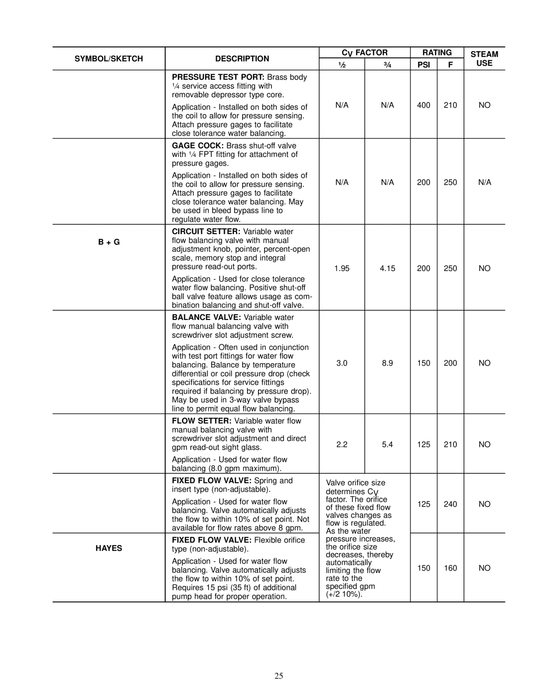
42 SERIES specifications
The Carrier 42 SERIES represents a cutting-edge solution in the realm of HVAC systems, meticulously designed to provide efficient heating, cooling, and ventilation for residential and commercial spaces. Known for their reliability and superior performance, these units combine advanced technologies with user-friendly features, catering to diverse climate needs.One of the standout features of the Carrier 42 SERIES is its energy efficiency. These units are equipped with high Seasonal Energy Efficiency Ratings (SEER) and Heating Seasonal Performance Factor (HSPF) ratings, which translate to reduced energy consumption and lower utility bills. The use of advanced inverter technology allows the compressor to adjust its speed and output according to the precise heating or cooling needs of a space, ensuring optimal comfort while minimizing energy waste.
In terms of operation, the Carrier 42 SERIES includes a variable speed compressor that not only enhances comfort but also ensures quieter operation. Unlike traditional systems, these units can run at lower speeds for longer periods, resulting in a more consistent indoor climate without the disruptive noise typically associated with HVAC systems.
Another significant aspect of the Carrier 42 SERIES is its robust construction and advanced materials. Built with durability in mind, these units feature weather-resistant cabinets and enhanced corrosion protection, ensuring a longer lifespan and reliable performance even in harsh environmental conditions.
Smart connectivity is also a hallmark of the Carrier 42 SERIES. Many models come with integrated Wi-Fi capabilities, allowing users to control their heating and cooling systems remotely via mobile apps. This feature enables homeowners to manage their indoor climate settings from anywhere, enhancing convenience and energy savings.
Furthermore, the Carrier 42 SERIES incorporates advanced air filtration systems designed to improve indoor air quality. These systems capture dust, allergens, and other airborne pollutants, contributing to a healthier living environment.
Overall, the Carrier 42 SERIES emerges as an exceptional choice for anyone seeking a reliable, efficient, and technologically advanced HVAC system. With its focus on energy efficiency, quiet operation, durability, smart home integration, and air quality improvement, it meets the demands of modern users while ensuring comfort throughout the year.

