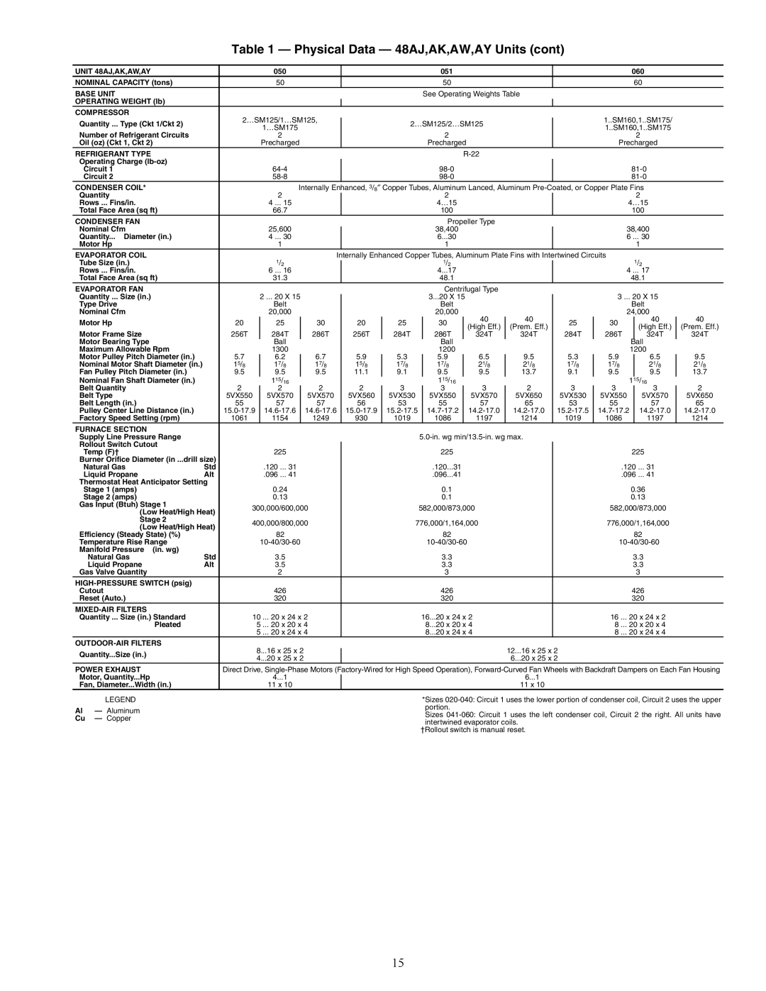
Table 1 — Physical Data — 48AJ,AK,AW,AY Units (cont)

UNIT 48AJ,AK,AW,AY


050


051


060


NOMINAL CAPACITY (tons)


50


50


60


BASE UNIT


See Operating Weights Table


OPERATING WEIGHT (lb)


COMPRESSOR


2…SM125/1…SM125,


1..SM160,1..SM175/


Quantity ... Type (Ckt 1/Ckt 2)


2…SM125/2…SM125


1…SM175


1..SM160,1..SM175


Number of Refrigerant Circuits


2


2


2


Oil (oz) (Ckt 1, Ckt 2)


Precharged


Precharged


Precharged


REFRIGERANT TYPE


R-22


Operating Charge (lb-oz)


Circuit 1


64-4


98-0


81-0


Circuit 2


58-8


98-0


81-0


CONDENSER COIL*


Internally Enhanced, 3/8Copper Tubes, Aluminum Lanced, Aluminum Pre-Coated, or Copper Plate Fins


Quantity


2


2


2


Rows ... Fins/in.


4 ... 15


4…15


4…15


Total Face Area (sq ft)


66.7


100


100


CONDENSER FAN


Propeller Type


Nominal Cfm


25,600


38,400


38,400


Quantity... Diameter (in.)


4 ... 30


6...30


6 ... 30


Motor Hp


1


1


1


EVAPORATOR COIL


Internally Enhanced Copper Tubes, Aluminum Plate Fins with Intertwined Circuits


Tube Size (in.)


1/2


1/2


1/2


Rows ... Fins/in.


6 ... 16


4...17


4 ... 17


Total Face Area (sq ft)


31.3


48.1


48.1


EVAPORATOR FAN


Centrifugal Type


Quantity ... Size (in.)


2 ... 20 X 15


3...20 X 15


3 ... 20 X 15


Type Drive


Belt


Belt


Belt


Nominal Cfm


20,000


20,000


24,000


Motor Hp


20


25


30


20


25


30


40


40


25


30


40


40


(High Eff.)


(Prem. Eff.)


(High Eff.)


(Prem. Eff.)

Motor Frame Size


256T


284T


286T


256T


284T


286T


324T


324T


284T


286T


324T


324T

Motor Bearing Type


Ball


Ball


Ball


Maximum Allowable Rpm


1300


1200


1200


Motor Pulley Pitch Diameter (in.)

5.7


6.2


6.7


5.9


5.3


5.9


6.5


9.5


5.3


5.9


6.5


9.5

Nominal Motor Shaft Diameter (in.)

15/8


17/8


17/8


15/8


17/8


17/8


21/8


21/8


17/8


17/8


21/8


21/8

Fan Pulley Pitch Diameter (in.)

9.5


9.5


9.5


11.1


9.1


9.5


9.5


13.7


9.1


9.5


9.5


13.7

Nominal Fan Shaft Diameter (in.)


115/16


115/16


1


15/16


Belt Quantity


2


2


2


2


3


3


3


2


3


3


3


2


Belt Type


5VX550


5VX570


5VX570


5VX560


5VX530


5VX550


5VX570


5VX650


5VX530


5VX550


5VX570


5VX650

Belt Length (in.)


55


57


57


56


53


55


57


65


53


55


57


65

Pulley Center Line Distance (in.)

15.0-17.9


14.6-17.6


14.6-17.6

15.0-17.9


15.2-17.5


14.7-17.2


14.2-17.0


14.2-17.0

15.2-17.5


14.7-17.2


14.2-17.0


14.2-17.0

Factory Speed Setting (rpm)

1061


1154


1249


930


1019


1086


1197


1214


1019


1086


1197


1214

FURNACE SECTION


Supply Line Pressure Range


5.0-in. wg min/13.5-in. wg max.


Rollout Switch Cutout


Temp (F)†


225


225


225


Burner Orifice Diameter (in ...drill size)


Natural Gas

Std


.120 ... 31


.120...31


.120 ... 31


Liquid Propane

Alt


.096 ... 41


.096...41


.096 ... 41


Thermostat Heat Anticipator Setting


Stage 1 (amps)


0.24


0.1


0.36


Stage 2 (amps)


0.13


0.1


0.13


Gas Input (Btuh) Stage 1

300,000/600,000


582,000/873,000


582,000/873,000


(Low Heat/High Heat)


Stage 2

400,000/800,000


776,000/1,164,000


776,000/1,164,000


(Low Heat/High Heat)


Efficiency (Steady State) (%)


82


82


82


Temperature Rise Range


10-40/30-60


10-40/30-60


10-40/30-60


Manifold Pressure

(in. wg)


Natural Gas

Std


3.5


3.3


3.3


Liquid Propane

Alt


3.5


3.3


3.3


Gas Valve Quantity


2


3


3


HIGH-PRESSURE SWITCH (psig)


Cutout


426


426


426


Reset (Auto.)


320


320


320


MIXED-AIR FILTERS


Quantity ... Size (in.) Standard

10 ... 20 x 24 x 2


16...20 x 24 x 2


16 ... 20 x 24 x 2


Pleated


5 ... 20 x 20 x 4


8...20 x 20 x 4


8 ... 20 x 20 x 4


5 ... 20 x 24 x 4


8...20 x 24 x 4


8 ... 20 x 24 x 4


OUTDOOR-AIR FILTERS


8...16 x 25 x 2


12...16 x 25 x 2


Quantity...Size (in.)


4...20 x 25 x 2


6...20 x 25 x 2


POWER EXHAUST


Direct Drive, Single-Phase Motors (Factory-Wired for High Speed Operation), Forward-Curved Fan Wheels with Backdraft Dampers on Each Fan Housing

Motor, Quantity...Hp


4...1


6...1


Fan, Diameter...Width (in.)


11 x 10


11 x 10


LEGEND


*Sizes 020-040: Circuit 1 uses the lower portion of condenser coil, Circuit 2 uses the upper

Al

Aluminum


portion.


Sizes 041-060: Circuit 1 uses the left condenser coil, Circuit 2 the right. All units have

Cu

Copper


intertwined evaporator coils.


†Rollout switch is manual reset.

15

Page 15
Image 15
Carrier 48AJ installation instructions 050 051 060 Nominal Capacity tons

48AJ specifications

The Carrier 48EJ, 48AW, 48EK, 48AJ, and 48EY024-068 are cutting-edge rooftop air conditioning units designed for commercial applications. These models are renowned for their reliability, energy efficiency, and innovative technologies aimed at providing optimal indoor comfort.

One of the standout features of these units is their advanced cooling and heating capabilities. They employ a multi-stage compressor system that allows for precise temperature control, accommodating various load requirements. This flexibility is particularly beneficial in commercial settings where the cooling load can fluctuate throughout the day.

Energy efficiency is paramount in today’s environmental landscape, and Carrier has ensured that these models meet stringent efficiency standards. They incorporate high-efficiency scroll compressors, which significantly reduce energy consumption while delivering powerful performance. The units are also equipped with variable speed fans that adjust airflow based on demand, further optimizing energy use.

In terms of construction, these rooftop units feature a robust design that enhances durability and longevity. The cabinet is constructed to withstand harsh weather conditions, ensuring reliable performance year-round. Additionally, the units are equipped with corrosion-resistant coatings, particularly useful in coastal environments where salt exposure can be a concern.

The Carrier 48EJ, 48AW, 48EK, 48AJ, and 48EY models utilize advanced controls and connectivity features, allowing for easy integration into building management systems. This connectivity enables remote monitoring and control, facilitating quick response to changing conditions and simplifying maintenance tasks.

Noise reduction is another key characteristic of these models. They are designed with sound-absorbing insulation and low-noise fan blades to ensure quiet operation, making them suitable for noise-sensitive environments such as schools and hospitals.

These units are also available with various options for air filtration and dehumidification. The use of high-efficiency air filters enhances indoor air quality by trapping dust, pollen, and other airborne particles. Enhanced dehumidification capabilities ensure that spaces remain comfortable even in humid conditions.

In conclusion, the Carrier 48EJ, 48AW, 48EK, 48AJ, and 48EY024-068 rooftop units are engineered to offer exceptional performance, energy efficiency, and durability. With their advanced technologies and user-friendly features, they stand out as reliable solutions for meeting diverse commercial cooling and heating needs, making them a popular choice for many businesses.