48EZ -- A
EXAMPLE: Assume that the size of test dial is 1 cu ft, one revolution takes 32 sec, and the heating value of the gas is 1050 Btu/ft3. Proceed as follows:
1.32 sec. to complete one revolution.
2.3600 ÷ 32 = 112.5.
3.112.5 x 1 =112.5 ft3 of gas flow/hr.
4.112.5 x 1050 = 118,125 Btuh input.
If the desired gas input is 115,000 Btuh, only a minor change in the manifold pressure is required.
Observe manifold pressure and proceed as follows to adjust gas input:
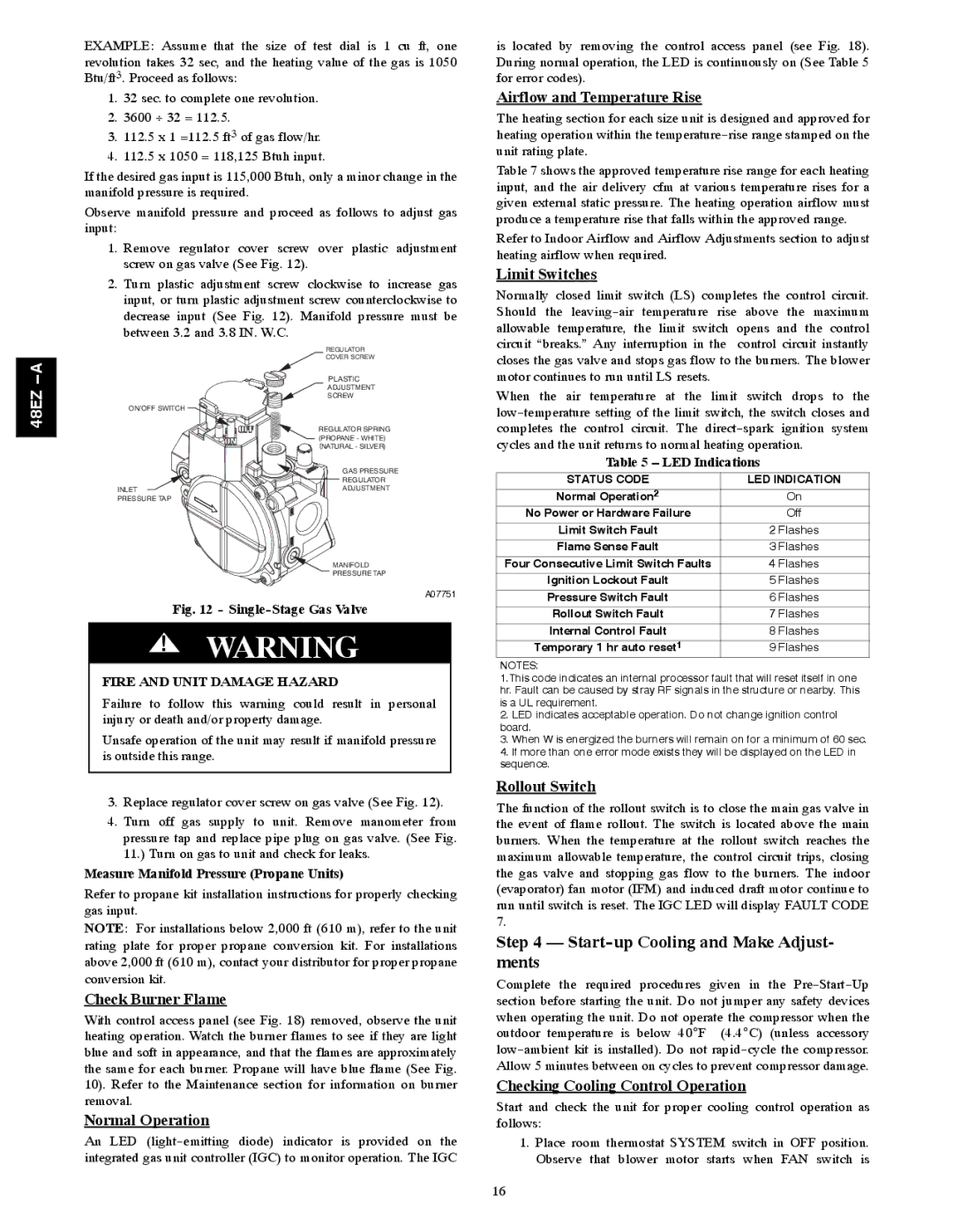
1.Remove regulator cover screw over plastic adjustment screw on gas valve (See Fig. 12).
2.Turn plastic adjustment screw clockwise to increase gas input, or turn plastic adjustment screw counterclockwise to decrease input (See Fig. 12). Manifold pressure must be between 3.2 and 3.8 IN. W.C.
| REGULATOR |
| COVER SCREW |
| PLASTIC |
| ADJUSTMENT |
| SCREW |
ON/OFF SWITCH |
|
| REGULATOR SPRING |
| (PROPANE - WHITE) |
| (NATURAL - SILVER) |
| GAS PRESSURE |
| REGULATOR |
INLET | ADJUSTMENT |
PRESSURE TAP |
|
| MANIFOLD |
| PRESSURE TAP |
A07751
Fig. 12 - Single-Stage Gas Valve
!WARNING
FIRE AND UNIT DAMAGE HAZARD
Failure to follow this warning could result in personal injury or death and/or property damage.
Unsafe operation of the unit may result if manifold pressure is outside this range.
3.Replace regulator cover screw on gas valve (See Fig. 12).
4.Turn off gas supply to unit. Remove manometer from pressure tap and replace pipe plug on gas valve. (See Fig. 11.) Turn on gas to unit and check for leaks.
Measure Manifold Pressure (Propane Units)
Refer to propane kit installation instructions for properly checking gas input.
NOTE: For installations below 2,000 ft (610 m), refer to the unit rating plate for proper propane conversion kit. For installations above 2,000 ft (610 m), contact your distributor for proper propane conversion kit.
Check Burner Flame
With control access panel (see Fig. 18) removed, observe the unit heating operation. Watch the burner flames to see if they are light blue and soft in appearance, and that the flames are approximately the same for each burner. Propane will have blue flame (See Fig. 10). Refer to the Maintenance section for information on burner removal.
Normal Operation
An LED
is located by removing the control access panel (see Fig. 18). During normal operation, the LED is continuously on (See Table 5 for error codes).
Airflow and Temperature Rise
The heating section for each size unit is designed and approved for heating operation within the
Table 7 shows the approved temperature rise range for each heating input, and the air delivery cfm at various temperature rises for a given external static pressure. The heating operation airflow must produce a temperature rise that falls within the approved range.
Refer to Indoor Airflow and Airflow Adjustments section to adjust heating airflow when required.
Limit Switches
Normally closed limit switch (LS) completes the control circuit. Should the
When the air temperature at the limit switch drops to the
Table 5 – LED Indications
STATUS CODE | LED INDICATION |
Normal Operation2 | On |
No Power or Hardware Failure | Off |
Limit Switch Fault | 2 Flashes |
Flame Sense Fault | 3 Flashes |
Four Consecutive Limit Switch Faults | 4 Flashes |
Ignition Lockout Fault | 5 Flashes |
Pressure Switch Fault | 6 Flashes |
Rollout Switch Fault | 7 Flashes |
Internal Control Fault | 8 Flashes |
Temporary 1 hr auto reset1 | 9 Flashes |
NOTES:
1.This code indicates an internal processor fault that will reset itself in one hr. Fault can be caused by stray RF signals in the structure or nearby. This is a UL requirement.
2.LED indicates acceptable operation. Do not change ignition control board.
3.When W is energized the burners will remain on for a minimum of 60 sec.
4.If more than one error mode exists they will be displayed on the LED in sequence.
Rollout Switch
The function of the rollout switch is to close the main gas valve in the event of flame rollout. The switch is located above the main burners. When the temperature at the rollout switch reaches the maximum allowable temperature, the control circuit trips, closing the gas valve and stopping gas flow to the burners. The indoor (evaporator) fan motor (IFM) and induced draft motor continue to run until switch is reset. The IGC LED will display FAULT CODE 7.
Step 4 — Start-up Cooling and Make Adjust- ments
Complete the required procedures given in the
Checking Cooling Control Operation
Start and check the unit for proper cooling control operation as follows:
1.Place room thermostat SYSTEM switch in OFF position. Observe that blower motor starts when FAN switch is
16