Manuals
/
Carrier
/
Household Appliance
/
Electric Heater
Carrier
48EZ(N)-A
installation instructions
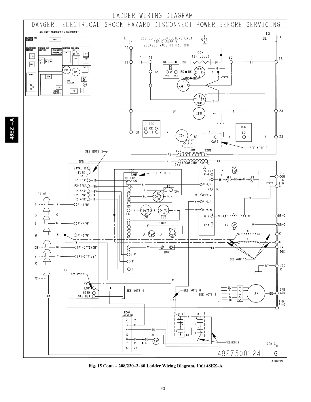
Cont. 208/230-3-60 Ladder Wiring Diagram, Unit 48EZ-A
Models:
48EZ(N)-A
1
30
41
41
Download
41 pages
38.93 Kb
27
28
29
30
31
32
33
34
Troubleshooting
Install
Unit Heating Rise Motor Wire
Dimension
Maintenance
Symptom Cause Remedy
Adjust Gas Input
Temperatures
Limit Switch
Page 30
Image 30
48EZ
A--
A10208L
Fig. 15 Cont. -
208/230-3-60
Ladder Wiring Diagram, Unit
48EZ-A
30
Page 29
Page 31
Page 30
Image 30
Page 29
Page 31
Contents
Table of Contents
Safety Considerations
Check Equipment
Receiving and Installation
Introduction
Provide Unit Support
48EZ-A24-36 Unit Dimensions
48EZ-A42-60 Unit Dimensions
Roof Curb Dimensions
Number
Rig and Place Unit
Field Fabricate Ductwork
Provide Clearances
Inspection
Connect Condensate Drain
Install Flue Hood
Install Gas Piping
Rigging/Lifting of Unit See Fig
Fire or Explosion Hazard
Sediment Trap
Install Duct Connections
Configuring Units for Downflow Vertical Discharge
Physical Data Unit 48EZ-A
Physical Data Unit 48EZ-A Cont’d
Maximum Gas Flow Capacity
Heating Inputs
High-Voltage Connections
Install Electrical Connections
Special Procedures for 208-V Operation
Unit Component Damage Hazard
Control Voltage Connections
Balance Point Setting-Thermidistat or Hybrid Thermostat
PRE-START-UP
Transformer Protection
Check for Refrigerant Leaks
Start-up Heating and Make Adjust- ments
START-UP
Unit Sequence of Operation
Adjust Gas Input
Check Gas Input
Unit Damage Hazard
Start-up Cooling and Make Adjust- ments
Gas Heating Fan Speed Set-up
Checking and Adjusting Refrigerant Charge
Indoor Airflow and Airflow Adjustments
Unit Operation Hazard
Two Cooling Fan Speeds Set-up Dehumidification feature used
Continuous Fan Operation
Color Coding for Indoor Fan Motor Leads
Dry Coil Air Delivery* Horizontal Unit 48EZ-A24-60
Unit Heating Rise Motor
Range Speed Color
Dry Coil Air Delivery* Horizontal Discharge Unit 48EZ-A24-60
1354 1290 1226 1158 1102 1046 981 918 843 55oF Heating Rise
Medium1
48EZ ---,NA48090
48EZ ---,NA48130
Unit Heating Rise Motor Wire
Downflow Cooling Standard CFM Scfm Economizer + Tons
Horizontal and Downflow Filter Pressure Drop Table IN. W.C
Unit Standard CFM Scfm Size
Cooling Standard CFM Scfm
48EZ a
208/230-1-60 Ladder Wiring Diagram, Unit 48EZ-A
208/230-3-60 Connection Wiring Diagram, Unit 48EZ-A
Cont. 208/230-3-60 Ladder Wiring Diagram, Unit 48EZ-A
Cooling Charging Table-Subcooling
Air Filter
Maintenance
Cleaning the Blower Motor and Wheel
Indoor Blower and Motor
Burner Ignition
Limit Switch
Induced Draft combustion air Blower Assembly
Main Burners
Electrical Controls and Wiring
Outdoor Fan
Refrigerant Circuit
Gas Input
Pressure Switches
Loss of Charge Switch
Indoor Airflow
High-Pressure Switch
Copeland Scroll Compressor Puron Refrigerant
Explosion Hazard
Unit Operation and Safety Hazard
Refrigerant System
Compressor Oil
Troubleshooting
START-UP Checklist
Puronr R-410A Quick Reference Guide
Troubleshooting Guide Cooling or Heat Pump Heating Mode
Symptom Cause Remedy
Troubleshooting Guide-Heating
Troubleshooting Guide-LED Error Codes
LED OFF
Preliminary Information Model no
Temperatures
Remove and Store in Job Files
III. START-UP Electrical Supply Voltage Compressor Amps
Top
Page
Image
Contents