48EZ -- A
2.Remove the current speed tap wire from the “LOW” terminal on the interface fan board (IFB) (See Fig. 13) and place vinyl cap over the connector on the wire.
3.Connect the desired speed tap wire to the “LOW” terminal on the interface fan board (IFB).
Two Cooling Fan Speeds Set-up (Dehumidification feature used)
IMPORTANT: Dehumidification control must open control circuit on humidity rise above set point.
Use of the dehumidification cooling fan speed requires use of either a 24 VAC dehumidistat or a thermostat which includes control of a 24 VAC dehumidistat connection. In either case, the dehumidification control must open the control circuit on humidity rise above the dehumidification set point.
1.Remove fan speed tap wire from the “LOW” terminal on the interface fan board (IFB) (See Fig. 13).
2.Determine correct normal cooling fan speed for unit and application. Add the wet coil pressure drop in Table 9 to the system static to determine the correct cooling airflow speed in Table 7 that will deliver the nominal cooling airflow as listed in Table 1 for each size.
3.Remove the vinyl cap off of the desired speed tap wire (Refer to Table 6 for color coding) for the normal cooling fan speed and place desired speed tap wire on “HIGH” on the interface board.
4.Refer to airflow tables (Table 7) to determine allowable speeds for the dehumidification cooling fan speed. In Table 7, speeds that are not allowed for dehumidification cooling are shaded.
5.Remove the vinyl cap off of the desired speed tap wire (Refer to Table 6 for color coding) for the dehumidification cooling fan speed and place desired speed tap wire on the “LOW” connection on the interface board (IFB). Verify that static pressure is in the acceptable range for the speed tap to be used for dehumidification cooling.
6.Use any spare vinyl plugs to cap any unused speed tap wires.
Continuous Fan Operation
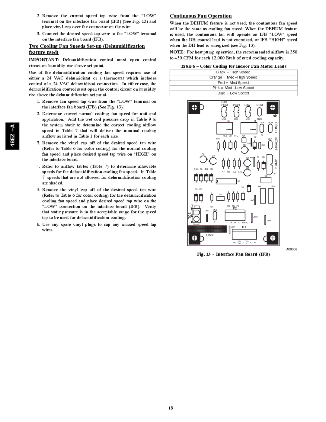
When the DEHUM feature is not used, the continuous fan speed will be the same as cooling fan speed. When the DEHUM feature is used, the continuous fan will operate on IFB “LOW” speed when the DH control lead is not energized, or IFB “HIGH” speed when the DH lead is energized (see Fig. 13).
NOTE: For heat pump operation, the recommended airflow is 350 to 450 CFM for each 12,000 Btuh of rated cooling capacity.
Table 6 – Color Coding for Indoor Fan Motor Leads
Black = High Speed
Orange =
Red = Med Speed
Pink =
Blue = Low Speed
|
|
|
| GAS |
|
|
|
|
|
|
|
|
|
| |
|
|
|
| HEAT |
| HIGH | LOW |
| COM |
|
| ||||
|
|
|
| QC6 |
|
| QC7 |
| QC4 |
| QC3 |
|
| ||
|
|
|
|
| K2 |
|
|
|
|
|
| K1 | DCR | QCR | CDM/C |
|
|
|
|
|
|
|
|
|
|
|
|
| |||
|
|
|
|
|
|
|
|
|
|
|
|
|
|
| |
|
|
|
| RL3 | C8 | R1L | Q1 |
|
| D2 | C |
|
| ||
|
|
|
|
|
|
|
| 24VAC/R | |||||||
|
|
|
| RI0 |
|
|
|
|
|
|
|
| QC1 | ||
|
|
|
|
|
|
|
|
|
|
|
|
| |||
|
|
|
|
|
|
|
|
|
| JM6 |
| RI2 |
| ||
|
|
|
|
|
|
|
|
| Q3 |
|
|
| |||
|
|
|
|
|
|
|
|
|
|
|
|
|
|
| |
| C9 |
| C4 |
|
|
|
|
|
|
|
|
|
|
|
|
|
|
|
|
|
|
|
|
| G1JM5 | RI | DL |
|
| ||
|
|
|
|
|
|
|
|
|
|
| 3 AMP | ||||
OILL C2 | D6 | D4 |
|
|
|
|
|
| G2 |
|
|
|
| ||
|
|
|
|
|
|
|
|
|
|
| |||||
|
|
|
|
|
|
|
|
|
|
|
| ||||
|
|
|
| A7 | R9 |
| AB | A15 |
|
|
|
|
| F1 | |
|
|
|
|
|
|
|
|
|
|
|
|
| C0 | ||
|
|
|
|
|
|
|
|
|
|
|
|
|
| ||
|
|
|
|
|
|
|
| U1 |
|
|
|
|
|
|
|
|
|
|
|
|
|
|
|
| C3 |
|
| R4 | RL4 | ||
D5 | D3 |
|
|
|
|
|
|
|
|
|
|
|
|
|
|
|
|
|
| C7 |
|
|
|
|
|
|
|
|
|
|
|
|
|
|
|
|
|
|
|
|
| JW3 |
|
|
| ||
P3 |
|
| R2 |
| R3 |
| R5 | R6 |
|
|
|
|
|
|
|
|
| JW7 | QCB |
|
| P2 |
|
|
|
|
|
|
| ||
SDL |
|
|
|
|
|
|
|
|
|
|
|
|
|
| |
|
|
|
|
|
|
|
|
|
|
| JW2 |
|
|
| |
|
|
| Y | Y | R | U | C | 24VAC |
|
|
| JW4 |
| ||
|
|
|
|
|
|
|
| ||||||||
|
|
|
|
|
| JW1 |
| P1 |
|
|
|
|
| ||
|
|
|
|
|
|
|
|
|
|
|
|
|
| ||
|
|
|
|
|
|
| W2 | Y2/ | G | Y1/ | C | R |
|
|
|
|
|
|
|
|
|
| DH | Y |
|
|
| ||||
A09058
Fig. 13 - Interface Fan Board (IFB)
18