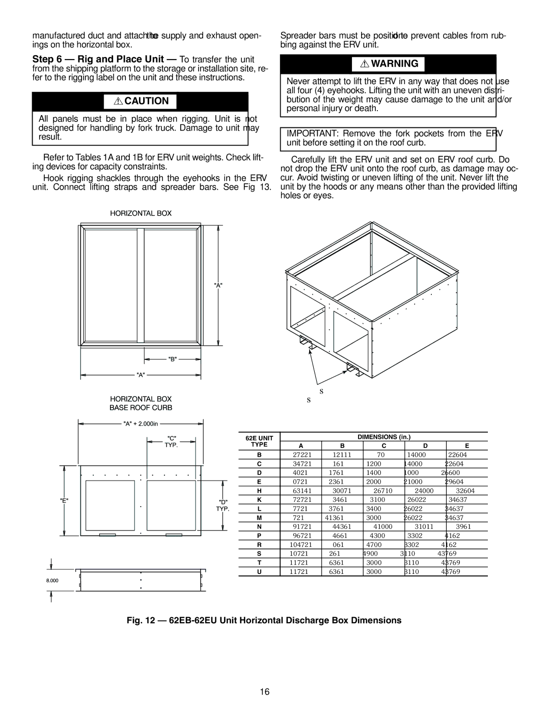
62E specifications
The Carrier 62E is a highly regarded air conditioning unit known for its efficiency, reliability, and advanced technology features. Designed to cater to both residential and light commercial applications, this model is recognized for its ability to provide optimal cooling performance even in challenging climates.One of the standout features of the Carrier 62E is its energy efficiency. The unit boasts a high Seasonal Energy Efficiency Ratio (SEER) rating, which ensures significant energy savings over time. This efficiency not only translates to lower energy bills for users but also contributes positively to environmental sustainability. The Carrier 62E is designed with eco-friendly refrigerants that minimize its carbon footprint while maintaining high performance levels.
In terms of technology, the Carrier 62E comes equipped with innovative smart controls. The unit can be integrated with smart home systems, allowing users to control their cooling preferences through their smartphones or other connected devices. This feature enhances convenience, enabling homeowners to adjust temperatures and monitor their system remotely, ensuring maximum comfort regardless of their location.
The 62E is engineered with a durable and robust build, ensuring long-lasting reliability. The components are crafted to withstand harsh weather conditions, making it a solid investment for users in varied climates. Additionally, the unit operates quietly, thanks to its advanced sound-dampening technologies, ensuring that indoor environments remain peaceful and undisturbed.
Installation of the Carrier 62E is straightforward, thanks to its versatile design and flexibility. The system can be configured for various ductwork arrangements, adapting seamlessly to different home layouts and existing infrastructure.
Another notable characteristic of the Carrier 62E is its advanced filtration system. The unit comes with a high-efficiency filter that captures airborne particles, allergens, and pollutants, promoting cleaner and healthier indoor air quality. This is an essential feature for households with allergy sufferers, as it helps create a more comfortable living space.
Overall, the Carrier 62E stands out as a leader in residential and light commercial air conditioning solutions. With its energy efficiency, state-of-the-art technology, durable design, and air quality improvements, it meets the diverse needs of modern users while providing remarkable comfort throughout the year. As climate considerations become increasingly important, the Carrier 62E remains a compelling choice for those seeking to enhance their home's comfort while being mindful of energy consumption and environmental impact.

