SYSTXCC4ZC01 specifications
The Carrier SYSTXCC4ZC01 is an advanced thermostat designed to enhance the comfort and efficiency of residential heating and cooling systems. This device offers a blend of cutting-edge technology and user-friendly features, making it an ideal choice for homeowners looking to optimize their indoor climate.One of the standout features of the SYSTXCC4ZC01 is its Wi-Fi connectivity. This allows users to control their HVAC systems remotely through a smartphone app, providing convenience and flexibility. Whether you’re at home, work, or on vacation, you can adjust the temperature, set schedules, and monitor energy consumption in real-time from virtually anywhere. This remote access not only enhances comfort but also supports energy savings by allowing homeowners to manage their heating and cooling efficiently.
The thermostat also boasts a sleek, modern design with a colorful touchscreen display. The intuitive interface makes it easy to navigate and customize settings. Furthermore, the SYSTXCC4ZC01 is equipped with advanced diagnostics capabilities. This feature not only helps in troubleshooting any potential issues but also assists homeowners in maintaining their systems more effectively, promoting longevity and reducing maintenance costs.
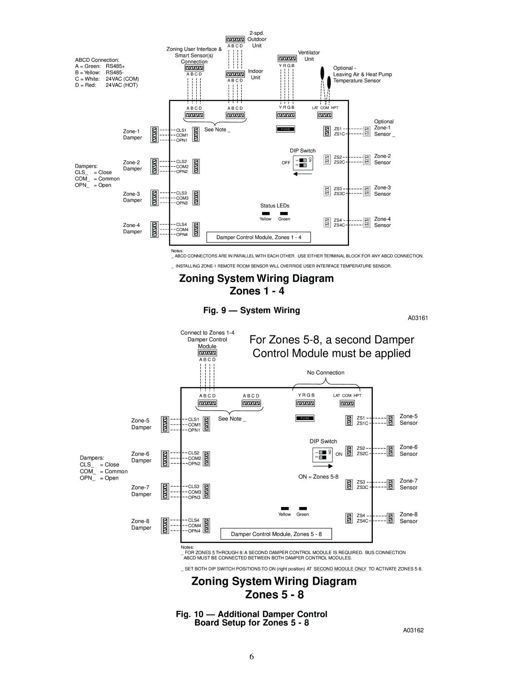
In terms of technology, the Carrier SYSTXCC4ZC01 is compatible with various heating and cooling systems, including single-stage and multi-stage setups. It supports heat pumps, gas furnaces, and air conditioning systems, offering versatility to meet different homeowner needs. The thermostat’s ability to handle multiple zones also allows for precise temperature control in larger homes, ensuring that each room maintains its desired level of comfort.
Energy efficiency is a core focus of the SYSTXCC4ZC01. The thermostat is designed to work in conjunction with Carrier’s Infinity system, integrating seamlessly to optimize performance and reduce energy costs. By using advanced algorithms, the thermostat learns the homeowner's preferences and schedules to minimize energy use without sacrificing comfort.
Additionally, the SYSTXCC4ZC01 includes smart alerts that notify users of filter changes, system maintenance, and extreme temperature fluctuations. This proactive feature empowers homeowners to make informed decisions about their HVAC systems, leading to increased efficiency and cost savings over time.
In summary, the Carrier SYSTXCC4ZC01 thermostat is a comprehensive solution for modern home climate control. With its Wi-Fi connectivity, intuitive interface, advanced diagnostics, compatibility with various systems, and focus on energy efficiency, it stands out as a leader in home comfort technology.

