Carrier ZN030-105, ZW, Z6, 48ZT, Z8075-105 B - Physical Data 48ZG,ZN055-070

Models: Z6 48ZG 48ZT ZW Z8075-105 ZN030-105

1 68
Download 68 pages 19.39 Kb
Page 5
Image 5

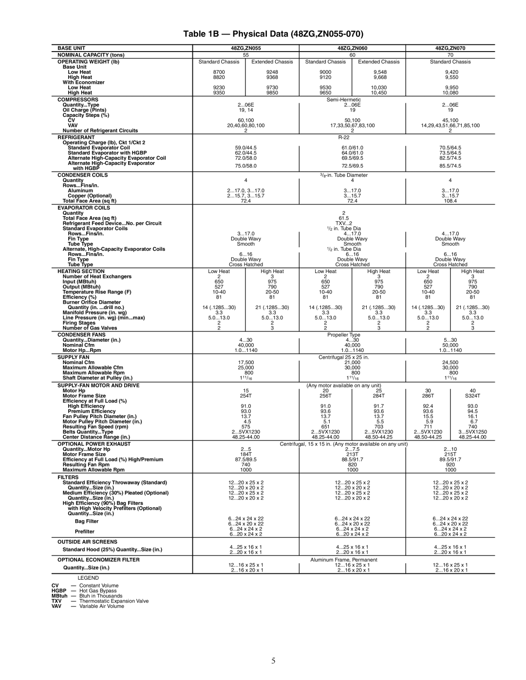
Table 1B — Physical Data (48ZG,ZN055-070)

BASE UNIT

48ZG,ZN055


48ZG,ZN060


48ZG,ZN070

NOMINAL CAPACITY (tons)


55


60


70

OPERATING WEIGHT (lb)

Standard Chassis


Extended Chassis


Standard Chassis


Extended Chassis


Standard Chassis


Base Unit


Low Heat

8700


9248


9000


9,548


9,420


High Heat

8820


9368


9120


9,668


9,550


With Economizer


Low Heat

9230


9730


9530


10,030


9,950


High Heat

9350


9850


9650


10,450


10,080

COMPRESSORS


Semi-Hermetic


Quantity...Type

2...06E


2...06E


2...06E


Oil Charge (Pints)

19, 14


19


19


Capacity Steps (%)


CV

60,100


50,100


45,100


VAV

20,40,60,80,100


17,33,50,67,83,100


14,29,43,51,66,71,85,100


Number of Refrigerant Circuits


2


2


2

REFRIGERANT


R-22


Operating Charge (lb), Ckt 1/Ckt 2


Standard Evaporator Coil

59.0/44.5


61.0/61.0


70.5/64.5


Standard Evaporator with HGBP

62.0/44.5


64.0/61.0


73.5/64.5


Alternate High-Capacity Evaporator Coil

72.0/58.0


69.5/69.5


82.5/74.5


Alternate High-Capacity Evaporator

75.0/58.0


72.5/69.5


85.5/74.5


with HGBP


CONDENSER COILS


3/8-in. Tube Diameter


Quantity


4


4


4


Rows...Fins/in.


Aluminum

2...17.0, 3...17.0


3...17.0


3...17.0


Copper (Optional)

2...15.7, 3...15.7


3...15.7


3...15.7


Total Face Area (sq ft)


72.4


72.4


108.4

EVAPORATOR COILS


Quantity


2


Total Face Area (sq ft)


61.5


Refrigerant Feed Device...No. per Circuit


TXV...2


Standard Evaporator Coils


1/2 in. Tube Dia


Rows...Fins/in.

3...17.0


4...17.0


4...17.0


Fin Type

Double Wavy


Double Wavy


Double Wavy


Tube Type

Smooth


Smooth


Smooth


Alternate, High-Capacity Evaporator Coils


1/2 in. Tube Dia


Rows...Fins/in.


6...16


6...16


6...16


Fin Type

Double Wavy


Double Wavy


Double Wavy


Tube Type

Cross Hatched


Cross Hatched


Cross Hatched

HEATING SECTION

Low Heat


High Heat


Low Heat


High Heat


Low Heat


High Heat


Number of Heat Exchangers

2


3


2


3


2


3


Input (MBtuh)

650


975


650


975


650


975


Output (MBtuh)

527


790


527


790


527


790


Temperature Rise Range (F)

10-40


20-50


10-40


20-50


10-40


20-50


Efficiency (%)

81


81


81


81


81


81


Burner Orifice Diameter


Quantity (in. ...drill no.)

14 (.1285...30)


21 (.1285...30)


14 (.1285...30)


21 (.1285...30)


14 (.1285...30)


21 (.1285...30)


Manifold Pressure (in. wg)

3.3


3.3


3.3


3.3


3.3


3.3


Line Pressure (in. wg) (min...max)

5.0...13.0


5.0...13.0


5.0...13.0


5.0...13.0


5.0...13.0


5.0...13.0


Firing Stages

2


2


2


2


2


2


Number of Gas Valves

2


3


2


3


2


3

CONDENSER FANS


Propeller Type


Quantity...Diameter (in.)


4...30


4...30


5...30


Nominal Cfm

40,000


40,000


50,000


Motor Hp...Rpm

1.0...1140


1.0...1140


1.0...1140

SUPPLY FAN


Centrifugal 25 x 25 in.


Nominal Cfm

17,500


21,000


24,500


Maximum Allowable Cfm

25,000


30,000


30,000


Maximum Allowable Rpm


800


800


800


Shaft Diameter at Pulley (in.)


111/16


111/16


111/16

SUPPLY-FAN MOTOR AND DRIVE


(Any motor available on any unit)


Motor Hp


15


20


25


30


40


Motor Frame Size


254T


256T


284T


286T


S324T


Efficiency at Full Load (%)


High Efficiency


91.0


91.0


91.7


92.4


93.0


Premium Efficiency


93.0


93.6


93.6


93.6


94.5


Fan Pulley Pitch Diameter (in.)


13.7


13.7


13.7


15.5


16.1


Motor Pulley Pitch Diameter (in.)


4.5


5.1


5.5


5.9


6.7


Resulting Fan Speed (rpm)


575


651


703


711


740


Belts Quantity...Type

2...5VX1230


2...5VX1230


2...5VX1230


2...5VX1230


3...5VX1250


Center Distance Range (in.)

48.25-44.00


48.25-44.00


48.50-44.25


48.50-44.25


48.25-44.00

OPTIONAL POWER EXHAUST


Centrifugal, 15 x 15 in. (Any motor available on any unit)


Quantity...Motor Hp


2...5


2...7.5


2...10


Motor Frame Size


184T


213T


215T


Efficiency at Full Load (%) High/Premium

87.5/89.5


88.5/91.7


89.5/91.7


Resulting Fan Rpm


740


820


920


Maximum Allowable Rpm


1000


1000


1000

FILTERS


Standard Efficiency Throwaway (Standard)

12...20 x 25 x 2


12...20 x 25 x 2


12...20 x 25 x 2


Quantity...Size (in.)

12...20 x 20 x 2


12...20 x 20 x 2


12...20 x 20 x 2


Medium Efficiency (30%) Pleated (Optional)

12...20 x 25 x 2


12...20 x 25 x 2


12...20 x 25 x 2


Quantity...Size (in.)

12...20 x 20 x 2


12...20 x 20 x 2


12...20 x 20 x 2


High Efficiency (90%) Bag Filters


with High Velocity Prefilters (Optional)


Quantity...Size (in.)

6...24 x 24 x 22


6...24 x 24 x 22


6...24 x 24 x 22


Bag Filter


6...24 x 20 x 22


6...24 x 20 x 22


6...24 x 20 x 22


Prefilter

6...24 x 24 x 2


6...24 x 24 x 2


6...24 x 24 x 2


6...20 x 24 x 2


6...20 x 24 x 2


6...20 x 24 x 2


OUTSIDE AIR SCREENS

4...25 x 16 x 1


4...25 x 16 x 1


4...25 x 16 x 1


Standard Hood (25%) Quantity...Size (in.)


2...20 x 16 x 1


2...20 x 16 x 1


2...20 x 16 x 1


OPTIONAL ECONOMIZER FILTER


Aluminum Frame, Permanent


Quantity...Size (in.)

12...16 x 25 x 1


12...16 x 25 x 1


12...16 x 25 x 1


2...16 x 20 x 1


2...16 x 20 x 1


2...16 x 20 x 1


LEGEND


CV

Constant Volume


HGBP — Hot Gas Bypass


MBtuh — Btuh in Thousands


TXV

Thermostatic Expansion Valve


VAV

Variable Air Volume


5

Page 5
Image 5
Carrier ZN030-105, ZW, Z6, 48ZT, Z8075-105 installation instructions B - Physical Data 48ZG,ZN055-070