| |
ELECTRONIC | |
THERMOSTAT | THERMOSTAT |
MODEL AC | INPUT |
| |
ELECTRONIC | |
THERMOSTAT | THERMOSTAT |
MODEL HP | INPUT |
|
|
|
|
|
|
|
24 VAC HOT |
| R |
|
|
| R |
24 VAC COMM |
|
|
|
|
|
|
|
|
|
|
|
| |
| C |
|
|
| C | |
|
|
|
|
|
|
|
|
|
|
|
|
|
|
HEAT STAGE 1 |
| W/W1 |
|
|
| W1 |
|
|
|
|
|
|
|
|
|
|
|
|
|
|
COOL STAGE 1 |
| Y/Y2 |
|
|
| Y1 |
|
|
|
|
| * |
|
|
|
|
|
| G | |
FAN |
| G | ||||
|
|
|
|
|
|
|
|
|
|
|
|
|
|
|
|
|
|
|
| W2 |
|
|
|
|
|
|
|
|
|
|
|
|
| Y2 |
|
|
|
|
|
| |
|
|
|
|
|
|
|
SEE NOTES 1 AND 3
| |
ELECTRONIC | |
THERMOSTAT | THERMOSTAT |
MODEL 2S | INPUT |
24 VAC HOT
24 VAC COMM
HEAT STAGE 1
COOL STAGE 1
FAN
HEAT STAGE 2
N/A
N/A
N/A
OUTDOOR
SENSOR CONNECTION
R![]() R
R
C ![]() C
C
|
| W/W1 |
|
| W1 | ||
|
|
|
|
|
|
|
|
|
|
|
|
|
|
|
|
|
|
| Y/Y2 |
|
| Y1 | |
|
|
|
|
|
|
|
|
|
|
|
|
| * G | ||
|
|
| G | ||||
|
|
|
|
|
|
|
|
|
|
|
|
|
|
|
|
|
|
|
|
|
| Y2 | |
|
|
|
|
|
|
|
|
|
|
| O/W2 |
|
| W2 | |
|
|
|
|
|
|
|
|
|
|
|
|
|
|
|
|
|
|
| Y1 |
|
|
|
|
|
|
|
|
|
|
|
|
|
|
| B |
|
|
|
|
|
|
|
|
|
|
|
|
|
|
| L |
|
| ||
|
|
|
|
|
| ||
|
|
| S1 |
|
| SEE NOTES 1, 2, AND 3 | |
|
|
|
|
|
| ||
|
|
| S2 |
|
|
|
|
|
|
|
|
|
|
|
|
|
|
|
|
|
|
|
|
24 VAC HOT
24 VAC COMM
HEAT STAGE 1
COOL STAGE 2
FAN
HEAT STAGE 2
COOL STAGE 1
N/A
TROUBLE
OUTDOOR
SENSOR CONNECTION
R![]() R
R
C ![]() C
C
|
| W/W1 |
|
| W1 | ||
|
|
|
|
|
|
|
|
|
|
|
|
|
|
|
|
|
|
| Y/Y2 |
|
| Y2 | |
|
|
|
|
|
|
|
|
|
|
|
|
| * G | ||
|
|
| G | ||||
|
|
|
|
|
|
|
|
|
|
|
|
|
|
|
|
|
|
|
|
|
|
|
|
|
|
| O/W2 |
|
| W2 | |
|
|
|
|
|
|
|
|
|
|
|
|
|
|
|
|
|
|
| Y1 |
|
| Y1 | |
|
|
|
|
|
|
|
|
|
|
|
|
|
|
|
|
|
|
| B |
|
|
|
|
|
|
|
|
|
|
|
|
|
|
| L |
|
|
|
|
|
|
|
|
|
|
|
|
|
|
| S1 |
|
| ||
|
|
|
|
|
| ||
|
|
| S2 |
|
| SEE NOTES 1, 2, AND 3 | |
|
|
|
|
|
| ||
|
|
|
|
|
| ||
|
|
|
|
| |||
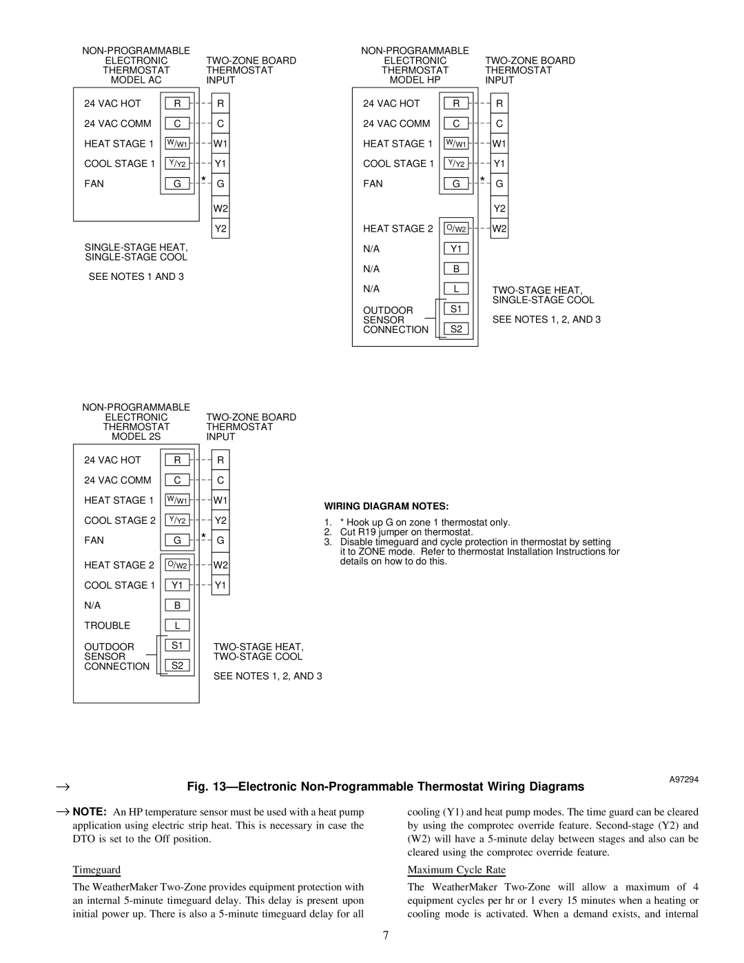
WIRING DIAGRAM NOTES:
1.* Hook up G on zone 1 thermostat only.
2.Cut R19 jumper on thermostat.
3.Disable timeguard and cycle protection in thermostat by setting it to ZONE mode. Refer to thermostat Installation Instructions for details on how to do this.
→ | A97294 |
Fig. 13ÐElectronic |
→NOTE: An HP temperature sensor must be used with a heat pump application using electric strip heat. This is necessary in case the DTO is set to the Off position.
Timeguard
The WeatherMaker
cooling (Y1) and heat pump modes. The time guard can be cleared by using the comprotec override feature.
Maximum Cycle Rate
The WeatherMaker
7