|
|
|
| |
|
| TYPICAL | HEAT PUMP | |
|
|
| ||
FAN COIL |
| |||
|
|
| ||
RH |
| R |
| R |
G |
| C |
| C |
|
|
|
| |
W2 |
| G |
|
|
|
|
| W2 | |
|
| W2 |
| |
W1 |
| Y/Y2 | * | Y2 |
|
| |||
Y1 |
| O | * | O |
Y2 |
| W3 |
| W3 |
|
|
|
| |
O |
| L | * |
|
| E | * |
| |
|
|
| ||
B |
| Y1 | * |
|
RC |
|
|
| Y1 |
| See notes 1, 2, 3, 9, and 11 |
| ||
A97310
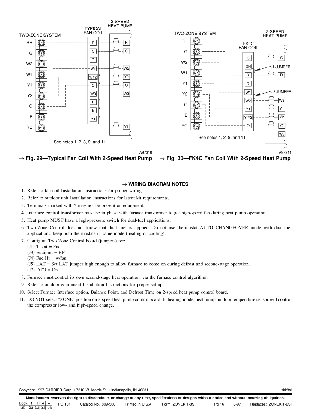
→Fig. 29ÐTypical Fan Coil With 2-Speed Heat Pump
HEAT PUMP | |||
|
| ||
RH | FK4C |
| |
|
| ||
G | FAN COIL |
| |
|
| ||
W2 | C | C | |
DH | J1 JUMPER | ||
| |||
W1 | R | R | |
| |||
Y1 | G |
| |
Y2 | W1 | J2 JUMPER | |
|
| ||
O | W2 | W2 | |
Y1 | Y1 | ||
| |||
B | Y/Y2 | Y2 | |
| |||
RC | O | O | |
| See notes 1, 2, 9, and 11 | W3 | |
|
| ||
|
| A97311 | |
→Fig. 30ÐFK4C Fan Coil With 2-Speed Heat Pump
→WIRING DIAGRAM NOTES
1.Refer to fan coil Installation Instructions for proper wiring.
2.Refer to outdoor unit Installation Instructions for latent kit requirements.
3.Terminals marked with * may not be present on equipment.
4.Interface control transformer must be in phase with furnace transformer to get
5.Heat pump MUST have a
6.
7.Configure
(J1)
(J3) Equipmt = HP
(J4) Fnc Ht = w/fan
(J5) LAT = Set LAT jumper high enough to allow furnace to come on during defrost and
(J7) DTO = On
8.Furnace must control its own
9.Refer to outdoor equipment Installation Instructions for proper set up.
10.Select Furnace Interface option, Balance Point, and Defrost Time on
11.DO NOT select "ZONE" position on
Copyright 1997 CARRIER Corp. · 7310 W. Morris St. · Indianapolis, IN 46231 | zkit8si |
|
|
Manufacturer reserves the right to discontinue, or change at any time, specifications or designs without notice and without incurring obligations.
Book | 1 | 1 | 4 | 4 | PC 101 | Catalog No. | Printed in U.S.A. | Form | Pg 16 | Replaces: | ||
| Tab | 3a | 5a | 2a | 5a |
|
|
|
|
|
|
|
