Manuals
/
Casio
/
Musical Instruments & Equipment
/
Electronic Keyboard
Casio
GZ-500
manual
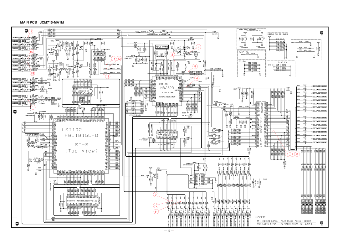
Main PCB JCM715-MA1M
Models:
GZ-500
1
19
26
26
Download
26 pages
46.02 Kb
16
17
18
19
20
21
22
23
Parts list
Block Diagram
Reset Circuit
Setting UP the Keyboard
Amp./Volume PCBs
Power Amplifier IC402 LA4598
Page 19
Image 19
MAIN PCB
JCM715-MA1M
17
2
16
3 14 13
5
15
12
1
4
6 7 8
9
10
11
— 19 —
Page 18
Page 20
Page 19
Image 19
Page 18
Page 20
Contents
GZ-500
Specifications
Contents
Operation
Setting UP the Keyboard
Setting Setting operation
Initial settings
Midi Message Setting Setting operation
Initial settings in The General Midi system
Transmitting Midi Messages
Selecting a Midi channel 1. Press the Midi button
Transmitting a digital effect type
Initial settings of Midi control change
Setting on/off of a Midi channel
Receiving Midi Messages
Receivable Messages
Transmittable Messages
KC7
Block Diagram
KEY Matrix
Circuit Description
Name Voltage For operation
Power Supply Circuit
Reset Circuit
Button Matrix
Pin No Terminal In/Out Function
Digital Signal Processor LSI102 HG51B155FD
CE1, Trsb
GND4
Block diagram of DSP and DAC circuit
KEY Controller LSI107 HG52E35P
DAC LSI104 UPD6376GS
Filter Block
LED Driving
Power Amplifier IC402 LA4598
Major Waveforms
Schematic Diagrams
Main PCB JCM715-MA1M
Console PCBs JCM715-CN1M/2M/3M
Keyboard PCBs M616T-KY1M/KY2M
Exploded View
Parts List
Amp./Volume PCBs
FOB Japan Code No Parts Name Specification Yen Unit Price
MA0800751A
Top
Page
Image
Contents