been triggered, signal becomes “Low”, and it will stop all alarm activities. Under
normal operation, signal remains “High”.
PIN 14. ALARM INPUT
To connect wire from ALARM INPUT ( PIN 14 ) to GND ( PIN 9 ) connector, DVR
will start recording and buzzer will be on. When alarm has been triggered, signal
becomes “Low”, and it will stop all alarm activities. Under normal operation, signal
remains “High”.
PIN 15. COM
Under normal operation COM connect with NC and disconnect with NO. But when
alarm triggered, COM disconnect with NC, and connect with NO.
4.Power input
Connect to power cord (standard package attached).
3.4Menu setup
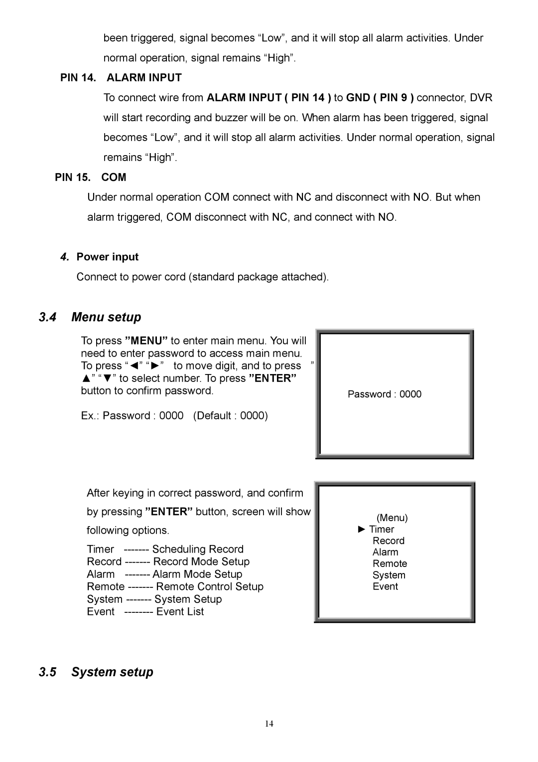
To press ”MENU” to enter main menu. You will need to enter password to access main menu. To press “◄” “►” to move digit, and to press ” ▲” “▼” to select number. To press ”ENTER” button to confirm password.
Ex.: Password : 0000 (Default : 0000)
Password : 0000
After keying in correct password, and confirm
by pressing ”ENTER” button, screen will show
following options.
Timer | Scheduling Record |
Record | Record Mode Setup |
Alarm | Alarm Mode Setup |
Remote | Remote Control Setup |
System | System Setup |
Event | Event List |
(Menu)
►Timer Record Alarm Remote System Event
3.5System setup
14
