Installation
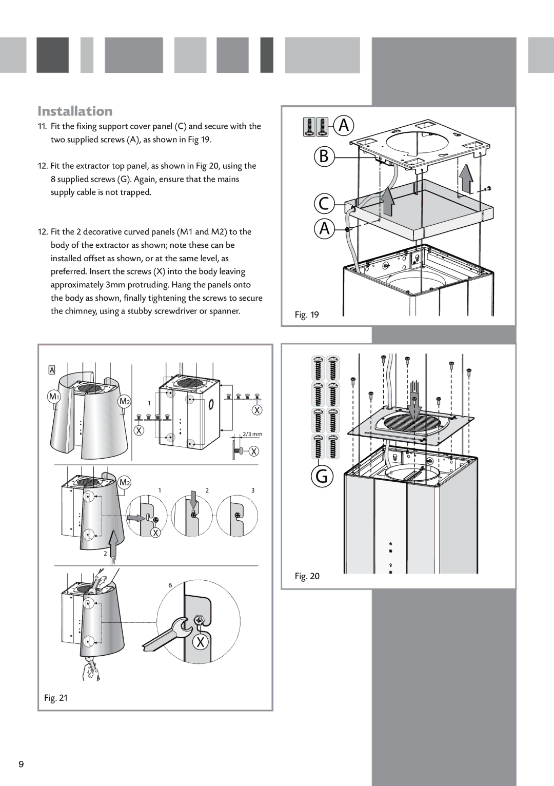
11.Fit the fixing support cover panel (C) and secure with the two supplied screws (A), as shown in Fig 19.
12.Fit the extractor top panel, as shown in Fig 20, using the 8 supplied screws (G). Again, ensure that the mains supply cable is not trapped.
12.Fit the 2 decorative curved panels (M1 and M2) to the body of the extractor as shown; note these can be installed offset as shown, or at the same level, as preferred. Insert the screws (X) into the body leaving approximately 3mm protruding. Hang the panels onto the body as shown, finally tightening the screws to secure the chimney, using a stubby screwdriver or spanner.
A |
|
|
|
|
M1 | M2 | 1 |
|
|
|
| X | ||
|
|
|
| |
|
| X |
| 2/3 mm |
|
|
|
| X |
| M2 | 1 | 2 | 3 |
|
| |||
|
| X |
|
|
| 2 |
|
|
|
|
|
| 6 |
|
|
|
| X |
|
Fig. 21 |
|
|
|
|
A |
B |
C |
A |
Fig. 19 |
G |
Fig. 20 |
9