GB |
|
| INJECTORS TABLE |
| |
|
|
|
|
| |
Cat: II 2H3+ | NOMINAL | REDUCED | G30/G31 | G20 | |
POWER | POWER | 20 mbar | |||
| |||||
BURNERS | [Hs - kW] | [Hs - kW] | Ø injector | Ø injector | |
[1/100 mm] | [1/100 mm] | ||||
|
|
| |||
|
|
|
|
| |
1,75 | 0,45 | 65 | 97 | ||
Rapid (R) | 3,00 | 0,75 | 85 | 115 | |
Triple ring (TR) | 3,50 | 1,50 | 95 | 135 | |
|
|
|
|
|
J
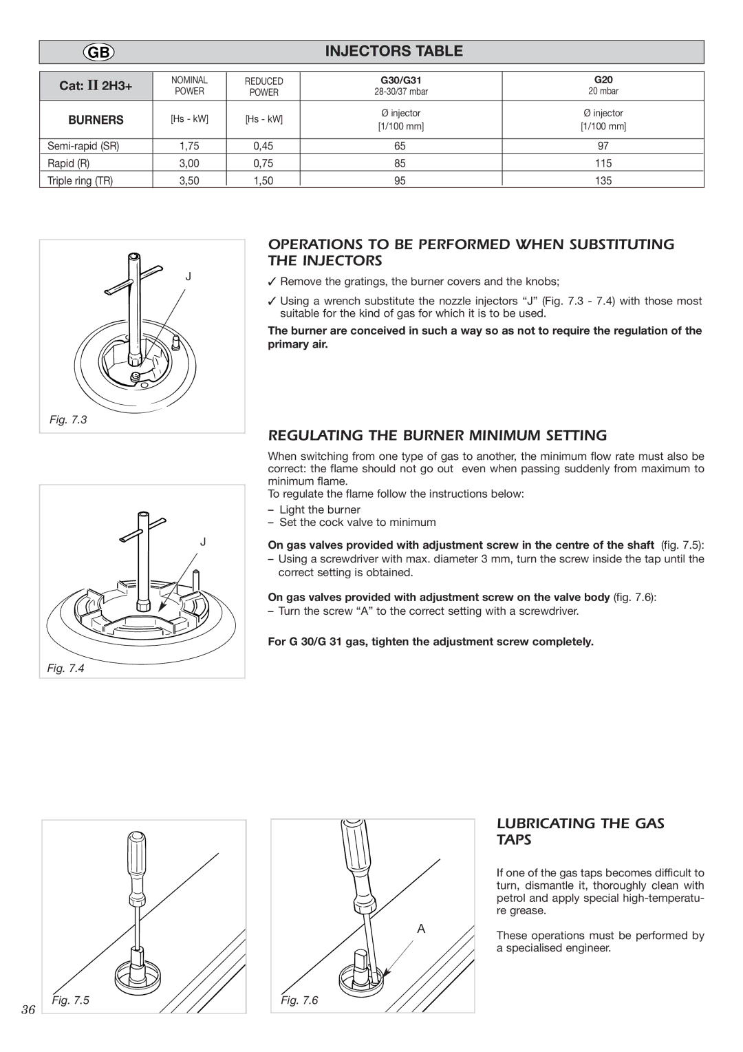
OPERATIONS TO BE PERFORMED WHEN SUBSTITUTING THE INJECTORS
✓Remove the gratings, the burner covers and the knobs;
✓Using a wrench substitute the nozzle injectors “J” (Fig. 7.3 - 7.4) with those most suitable for the kind of gas for which it is to be used.
The burner are conceived in such a way so as not to require the regulation of the primary air.
Fig. 7.3
REGULATING THE BURNER MINIMUM SETTING
J
Fig. 7.4
When switching from one type of gas to another, the minimum flow rate must also be correct: the flame should not go out even when passing suddenly from maximum to minimum flame.
To regulate the flame follow the instructions below:
–Light the burner
–Set the cock valve to minimum
On gas valves provided with adjustment screw in the centre of the shaft (fig. 7.5):
–Using a screwdriver with max. diameter 3 mm, turn the screw inside the tap until the correct setting is obtained.
On gas valves provided with adjustment screw on the valve body (fig. 7.6):
– Turn the screw “A” to the correct setting with a screwdriver.
For G 30/G 31 gas, tighten the adjustment screw completely.
Fig. 7.5 |
36 |
A |
Fig. 7.6 |
LUBRICATING THE GAS TAPS
If one of the gas taps becomes difficult to turn, dismantle it, thoroughly clean with petrol and apply special
These operations must be performed by a specialised engineer.