6.Measure distance between fireplace’s flue outlet (top of Sound Reducer) and fan inlet. Cut flexible duct and insulate with insulation sleeve sections using noise cone for ease of mounting. Please note that wherever possible use continuous length pipe with- out joints.
7.Apply silicone at both ends, and attach flex pipe to collars. Secure with clamps (provided). For addition- al reinforcement, it is recommended that three (3) sheet metal screws be used at each joint to prevent pipe from accidentally separating.
8.If fan is located at vent terminal, connect it by first sealing the joints with silicone. Again use three (3) sheet metal screws for each joint.
9.Seal all joints with aluminum vent pipe tape and cover with insulation. Joints between fan and vent terminal must be absolutely air and water tight to prevent flue gas or condensation leakage.
10.Support venting duct with plumber’s strap (supplied by installer). On horizontal runs support vent pipe every 36” (914mm) to prevent it from sagging.
11.Enclose venting system, if necessary leaving at least 1” (25 mm) clearance between insulation and combustible materials and 6” (152 mm) between fan housing and combustibles.
Majestic® Fireplaces Power Venting System
Electrical Wiring
Electrical connections and grounding must be in ac- cordance with the Canadian Electrical Code, C22.1 Part 1 and in U.S.A., National Electrical Code ANSI/NFPA70 and/or local codes where applicable.
Operation Sequence of 24 VAC
Controlled Appliance
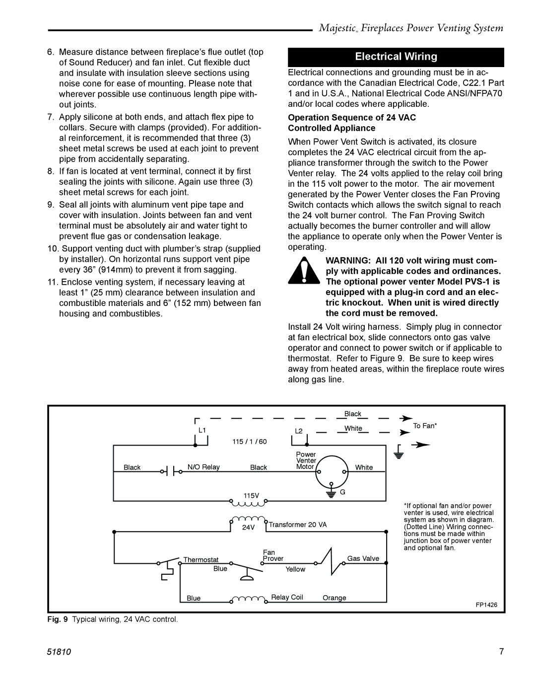
When Power Vent Switch is activated, its closure completes the 24 VAC electrical circuit from the ap- pliance transformer through the switch to the Power Venter relay. The 24 volts applied to the relay coil bring in the 115 volt power to the motor. The air movement generated by the Power Venter closes the Fan Proving Switch contacts which allows the switch signal to reach the 24 volt burner control. The Fan Proving Switch actually becomes the burner controller and will allow the appliance to operate only when the Power Venter is operating.
WARNING: All 120 volt wiring must com- ply with applicable codes and ordinances. The optional power venter Model
Install 24 Volt wiring harness. Simply plug in connector at fan electrical box, slide connectors onto gas valve operator and connect to power switch or if applicable to thermostat. Refer to Figure 9. Be sure to keep wires away from heated areas, within the fireplace route wires along gas line.
|
|
|
| Black |
| L1 |
| L2 | White |
|
| 115 / 1 / 60 |
|
|
|
|
| Power |
|
Black | N/O Relay | Black | Venter | White |
Motor | ||||
|
| 115V |
| G |
|
|
|
| |
|
| 24V | Transformer 20 VA | |
|
|
|
| |
| Thermostat | Fan | Gas Valve | |
| Prover | |||
| Blue |
| Yellow |
|
| Blue |
| Relay Coil | Orange |
To Fan*
*If optional fan and/or power venter is used, wire electrical system as shown in diagram. (Dotted Line) Wiring connec- tions must be made within junction box of power venter and optional fan.
FP1426
Fig. 9 Typical wiring, 24 VAC control.
51810 | 7 |