i4000 - Quad |
|
User Manual | Version: 1.2 |
3.2.3.M-MODULE INTERFACE CONNECTOR
The following table provides signal names for the
Pin | Row A | Row B |
Number |
|
|
01 | CS* | GND |
|
|
|
02 | A01 | +5V |
|
|
|
03 | A02 | +12V |
|
|
|
04 | A03 | |
|
|
|
05 | A04 | GND |
|
|
|
06 | A05 | DREQ* |
|
|
|
07 | A06 | DACK* |
|
|
|
08 | A07 | GND |
|
|
|
09 | D08 | D00 |
|
|
|
10 | D09 | D01 |
|
|
|
11 | D10 | D02 |
|
|
|
12 | D11 | D03 |
|
|
|
13 | D12 | D04 |
|
|
|
14 | D13 | D05 |
|
|
|
15 | D14 | D06 |
|
|
|
16 | D15 | D07 |
|
|
|
17 | DS1* | DS0* |
|
|
|
18 | DTACK* | WRITE* |
|
|
|
19 | IACK* | IRQ* |
|
|
|
20 | RESET* | SYSCLK |
|
|
|
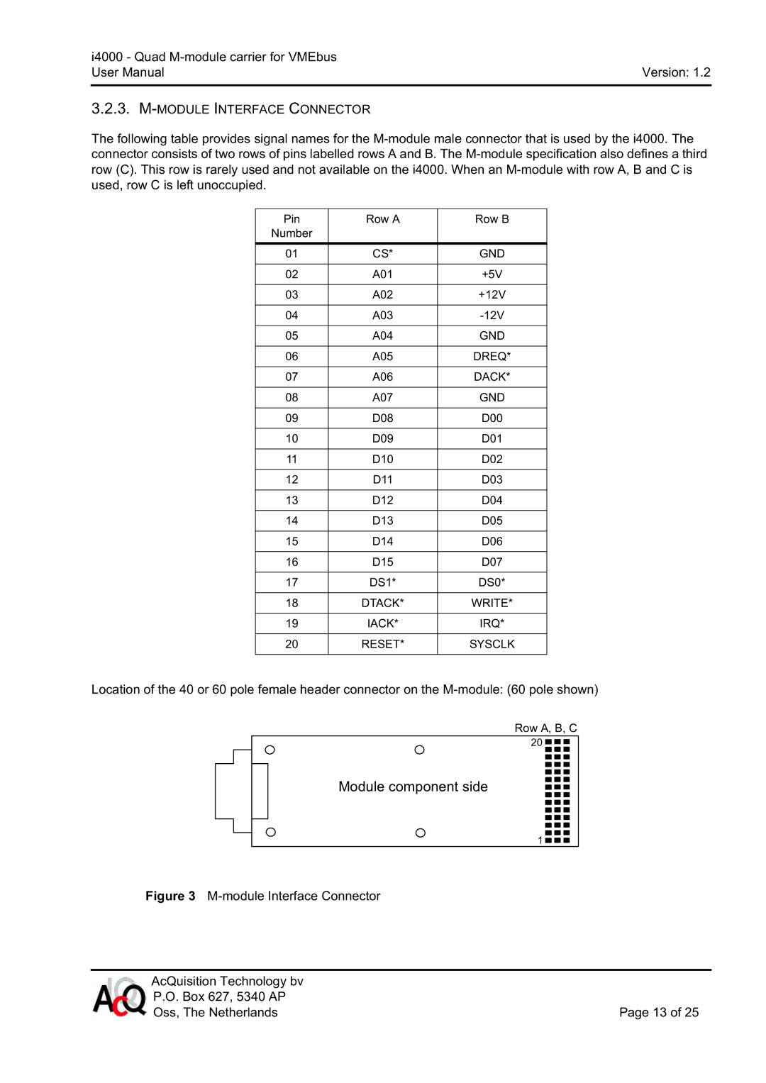
Location of the 40 or 60 pole female header connector on the
Row A, B, C
20 ![]()
![]()
![]()
Module component side
1 ![]()
![]()
![]()
Figure 3 M-module Interface Connector
AcQuisition Technology bv |
|
P.O. Box 627, 5340 AP |
|
Oss, The Netherlands | Page 13 of 25 |