i4000 - Quad |
|
User Manual | Version: 1.2 |
4.4.VMEBUS P1 CONNECTOR ASSIGNMENTS
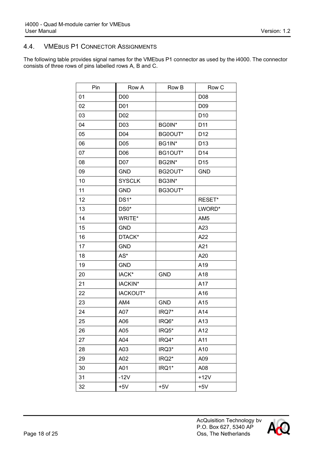
The following table provides signal names for the VMEbus P1 connector as used by the i4000. The connector consists of three rows of pins labelled rows A, B and C.
Pin | Row A | Row B | Row C |
|
|
|
|
01 | D00 |
| D08 |
|
|
|
|
02 | D01 |
| D09 |
|
|
|
|
03 | D02 |
| D10 |
|
|
|
|
04 | D03 | BG0IN* | D11 |
|
|
|
|
05 | D04 | BG0OUT* | D12 |
|
|
|
|
06 | D05 | BG1IN* | D13 |
|
|
|
|
07 | D06 | BG1OUT* | D14 |
|
|
|
|
08 | D07 | BG2IN* | D15 |
|
|
|
|
09 | GND | BG2OUT* | GND |
|
|
|
|
10 | SYSCLK | BG3IN* |
|
|
|
|
|
11 | GND | BG3OUT* |
|
|
|
|
|
12 | DS1* |
| RESET* |
|
|
|
|
13 | DS0* |
| LWORD* |
|
|
|
|
14 | WRITE* |
| AM5 |
|
|
|
|
15 | GND |
| A23 |
|
|
|
|
16 | DTACK* |
| A22 |
|
|
|
|
17 | GND |
| A21 |
|
|
|
|
18 | AS* |
| A20 |
|
|
|
|
19 | GND |
| A19 |
|
|
|
|
20 | IACK* | GND | A18 |
|
|
|
|
21 | IACKIN* |
| A17 |
|
|
|
|
22 | IACKOUT* |
| A16 |
|
|
|
|
23 | AM4 | GND | A15 |
|
|
|
|
24 | A07 | IRQ7* | A14 |
|
|
|
|
25 | A06 | IRQ6* | A13 |
|
|
|
|
26 | A05 | IRQ5* | A12 |
|
|
|
|
27 | A04 | IRQ4* | A11 |
|
|
|
|
28 | A03 | IRQ3* | A10 |
|
|
|
|
29 | A02 | IRQ2* | A09 |
|
|
|
|
30 | A01 | IRQ1* | A08 |
|
|
|
|
31 |
| +12V | |
|
|
|
|
32 | +5V | +5V | +5V |
|
|
|
|
| AcQuisition Technology bv |
| P.O. Box 627, 5340 AP |
Page 18 of 25 | Oss, The Netherlands |