3 WALL CONSOLE INSTALLATION
![]() WARNING
WARNING
Verify there is NO power to the opener before installing wall console wires and wall console.
![]() CAUTION
CAUTION
Staples which are too tight can cut or pinch wires. Cut or pinched wires can cause the wall console to stop working. When using the insulated staples, make sure you fasten them only as tightly as needed to hold the wire snugly.
![]() WARNING
WARNING
Use of any other wall control can cause the door to operate unexpectedly and the light not to work. Use only the included wall button.
NOTE: For Wall Console,wire and insulated staples locate Bags 6 and 7 from Box 2.
1.Wall Console location.
Wall Console location should be in direct sight of door.
It should be at least five feet (5') above floor to prevent small children from operating door.
It must be away from any moving parts. (You should NOT be able to reach the garage door while standing at Wall Console.)
Wall Console board screw connections are polarized.
2a. Wiring (If pre-wired).
FOR
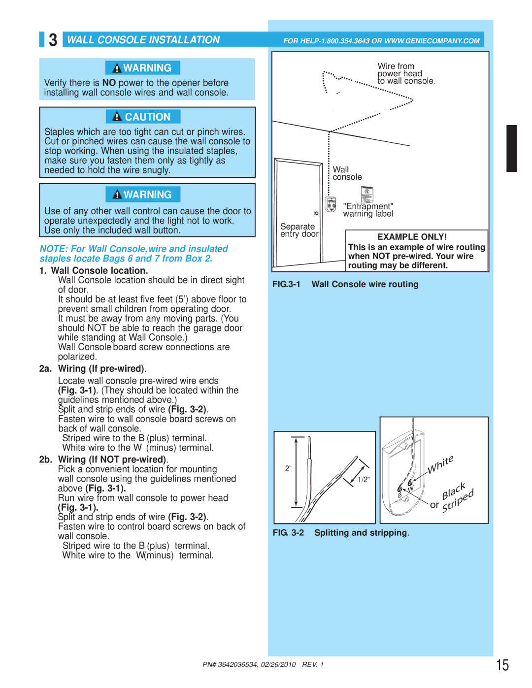
Wire from |
power head |
to wall console. |
Wall console
"Entrapment" warning label
Separate |
|
entry door | EXAMPLE ONLY! |
|
This is an example of wire routing when NOT
FIG.3-1 Wall Console wire routing
Locate wall console
Split and strip ends of wire (Fig.
Fasten wire to wall console board screws on back of wall console.
–Striped wire to the B (plus) terminal.
–White wire to the W (minus) terminal.
2b. Wiring (If NOT
Pick a convenient location for mounting |
wall console using the guidelines mentioned |
above (Fig. |
Run wire from wall console to power head |
(Fig. |
Split and strip ends of wire (Fig. |
Fasten wire to control board screws on back of |
2"![]()
![]() 1/2"
1/2"
|
| White | |
B | W |
| Black |
|
| ||
| or | Striped | |
|
| ||
|
|
| |
wall console. |
– Striped wire to the B (plus) terminal. |
– White wire to the W (minus) terminal. |
FIG. 3-2 Splitting and stripping.
PN# 3642036534, 02/26/2010 REV. 1 | 15 |
|