TM
Power Active On
A B C
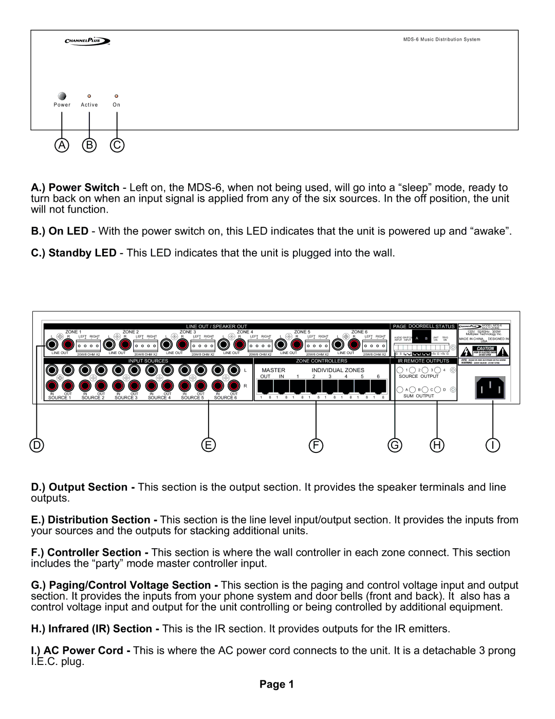
A.) Power Switch - Left on, the
B.) On LED - With the power switch on, this LED indicates that the unit is powered up and “awake”. C.) Standby LED - This LED indicates that the unit is plugged into the wall.
LINE OUT / SPEAKER OUT
| ZONE 1 |
|
| ZONE 2 |
|
| ZONE 3 |
|
| ZONE 4 |
|
| ZONE 5 |
|
| ZONE 6 |
| ||||||
L | R | LEFT | RIGHT | L | R | LEFT | RIGHT | L | R | LEFT | RIGHT | L | R | LEFT | RIGHT | L | R | LEFT | RIGHT | L | R | LEFT | RIGHT |
|
| - + | - + |
|
| - + | - + |
|
| - + | - + |
|
| - + | - + |
|
| - + | - + |
|
| - + | - + |
LINE OUT | 20W/8 OHM X2 | LINE OUT | 20W/8 OHM X2 | LINE OUT | 20W/8 OHM X2 | LINE OUT | 20W/8 OHM X2 | LINE OUT | 20W/8 OHM X2 | LINE OUT | 20W/8 OHM X2 |
|
|
|
|
|
|
|
|
|
|
| INPUT SOURCES |
|
|
|
|
|
| ZONE CONTROLLERS |
|
| |||||
|
|
|
|
|
|
|
|
|
|
| L | MASTER |
| INDIVIDUAL ZONES |
| ||||
|
|
|
|
|
|
|
|
|
|
|
| OUT | IN | 1 | 2 | 3 | 4 | 5 | 6 |
|
|
|
|
|
|
|
|
|
|
| R |
|
|
|
|
|
|
|
|
IN | OUT | IN | OUT | IN | OUT | IN | OUT | IN | OUT | IN | OUT |
|
|
|
|
|
|
|
|
SOURCE 1 | SOURCE 2 | SOURCE 3 | SOURCE 4 | SOURCE 5 | SOURCE 6 | 1 8 1 | 8 | 1 8 | 1 | 8 1 | 8 1 8 | 1 8 | 1 8 | ||||||
PAGE DOORBELL STATUS |
|
| ||||||||||||||||
|
|
|
|
|
|
|
|
|
|
|
|
|
|
|
| MODEL | ||
|
|
|
|
|
|
|
|
|
|
|
|
|
|
|
|
|
|
|
|
|
|
|
|
|
|
|
|
|
|
|
|
| 120V | 50/60Hz | 300W | ||
|
|
|
|
|
|
|
|
|
|
|
|
|
| Multiplex Technology Inc. | ||||
| AUDIO SWITCH | A | B | UNIT | TRIG | MADE IN CHINA DESIGNED IN | ||||||||||||
| INPUT INPUT | ON | ON | |||||||||||||||
|
|
|
|
|
|
|
|
|
|
|
|
|
|
|
| USA |
|
|
|
|
|
|
|
|
|
|
|
|
|
|
|
|
|
| CAUTION |
| |
| G S |
|
|
|
| +5v G +5v G |
| RISK OF ELECTRIC SHOCK |
| |||||||||
|
|
|
|
|
|
| DO NOT OPEN |
|
| |||||||||
|
|
|
|
|
|
|
|
|
|
|
|
|
|
|
|
|
|
|
| IR REMOTE OUTPUTS | WARNING: SHOCK HAZARD - DO NOT OPEN. | ||||||||||||||||
|
|
|
|
|
|
|
|
|
|
|
|
|
| AVIS: RISQUE DE CHOC | ||||
|
|
|
|
|
|
|
|
|
|
|
|
|
|
|
|
|
|
|
|
|
|
|
|
|
|
|
|
|
|
|
|
|
|
|
|
|
|
1 2 3 4
SOURCE OUTPUT
A B C D
SUM OUTPUT
DEFG H I
D.) Output Section - This section is the output section. It provides the speaker terminals and line outputs.
E.) Distribution Section - This section is the line level input/output section. It provides the inputs from your sources and the outputs for stacking additional units.
F.) Controller Section - This section is where the wall controller in each zone connect. This section includes the “party” mode master controller input.
G.) Paging/Control Voltage Section - This section is the paging and control voltage input and output section. It provides the inputs from your phone system and door bells (front and back). It also has a control voltage input and output for the unit controlling or being controlled by additional equipment.
H.) Infrared (IR) Section - This is the IR section. It provides outputs for the IR emitters.
I.) AC Power Cord - This is where the AC power cord connects to the unit. It is a detachable 3 prong I.E.C. plug.
Page 1