OUTPUT SECTION
LINE OUT / SPEAKER OUT
ZONE 1 | ZONE 2 | ZONE 3 | ZONE 4 | ZONE 5 | ZONE 6 |
LR
LINE OUT
LEFT RIGHT - + - +
20W/8 OHM X2 |
LR
LINE OUT
LEFT RIGHT - + - +
20W/8 OHM X2 |
LR
LINE OUT
LEFT RIGHT - + - +
20W/8 OHM X2 |
LR
LINE OUT
LEFT RIGHT - + - +
20W/8 OHM X2 |
LR
LINE OUT
LEFT RIGHT - + - +
20W/8 OHM X2 |
LR
LINE OUT
LEFT RIGHT - + - +
20W/8 OHM X2 |
12
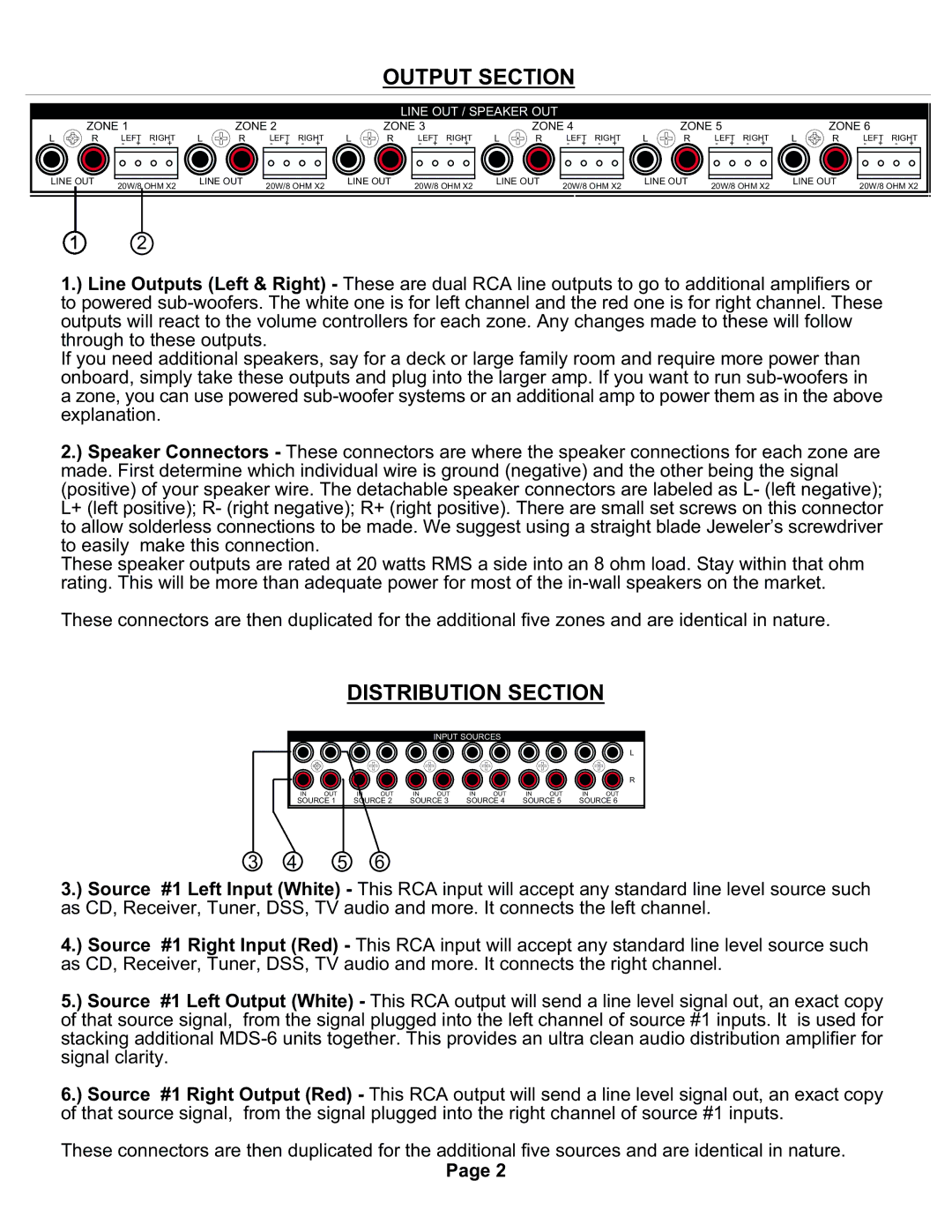
1.) Line Outputs (Left & Right) - These are dual RCA line outputs to go to additional amplifiers or to powered
If you need additional speakers, say for a deck or large family room and require more power than onboard, simply take these outputs and plug into the larger amp. If you want to run
2.) Speaker Connectors - These connectors are where the speaker connections for each zone are made. First determine which individual wire is ground (negative) and the other being the signal (positive) of your speaker wire. The detachable speaker connectors are labeled as L- (left negative); L+ (left positive); R- (right negative); R+ (right positive). There are small set screws on this connector to allow solderless connections to be made. We suggest using a straight blade Jeweler’s screwdriver to easily make this connection.
These speaker outputs are rated at 20 watts RMS a side into an 8 ohm load. Stay within that ohm rating. This will be more than adequate power for most of the
These connectors are then duplicated for the additional five zones and are identical in nature.
DISTRIBUTION SECTION
INPUT SOURCES
L
R
IN | OUT | IN | OUT | IN | OUT | IN | OUT | IN | OUT | IN | OUT |
SOURCE 1 | SOURCE 2 | SOURCE 3 | SOURCE 4 | SOURCE 5 | SOURCE 6 | ||||||
3 4 5 6
3.) Source #1 Left Input (White) - This RCA input will accept any standard line level source such as CD, Receiver, Tuner, DSS, TV audio and more. It connects the left channel.
4.) Source #1 Right Input (Red) - This RCA input will accept any standard line level source such as CD, Receiver, Tuner, DSS, TV audio and more. It connects the right channel.
5.) Source #1 Left Output (White) - This RCA output will send a line level signal out, an exact copy of that source signal, from the signal plugged into the left channel of source #1 inputs. It is used for stacking additional
6.) Source #1 Right Output (Red) - This RCA output will send a line level signal out, an exact copy of that source signal, from the signal plugged into the right channel of source #1 inputs.
These connectors are then duplicated for the additional five sources and are identical in nature.
Page 2
