CONTROLLER SECTION | ||||||||||||||||||||||||||
|
|
|
|
|
|
|
|
|
|
|
|
|
|
|
|
|
|
|
|
|
|
|
|
|
|
|
|
|
|
|
|
|
|
| ZONE CONTROLLERS |
|
|
|
|
|
|
|
| ||||||||||
| MASTER |
|
|
|
|
|
| INDIVIDUAL ZONES |
|
|
|
|
| |||||||||||||
| OUT |
| IN |
|
| 1 |
| 2 |
| 3 |
| 4 |
| 5 |
|
| 6 |
|
| |||||||
|
|
|
|
|
|
|
|
|
|
|
|
|
|
|
|
|
|
|
|
|
|
|
|
|
|
|
| 1 | 8 | 1 |
| 8 | 1 |
| 8 | 1 |
| 8 | 1 |
| 8 | 1 |
| 8 | 1 |
| 8 | 1 | 8 |
| |||
7 |
|
|
| 8 |
|
|
|
|
|
|
|
| 9 |
|
|
|
|
|
|
|
|
|
|
| ||
|
|
|
|
|
|
|
|
|
|
|
|
|
|
|
|
|
|
|
|
|
| |||||
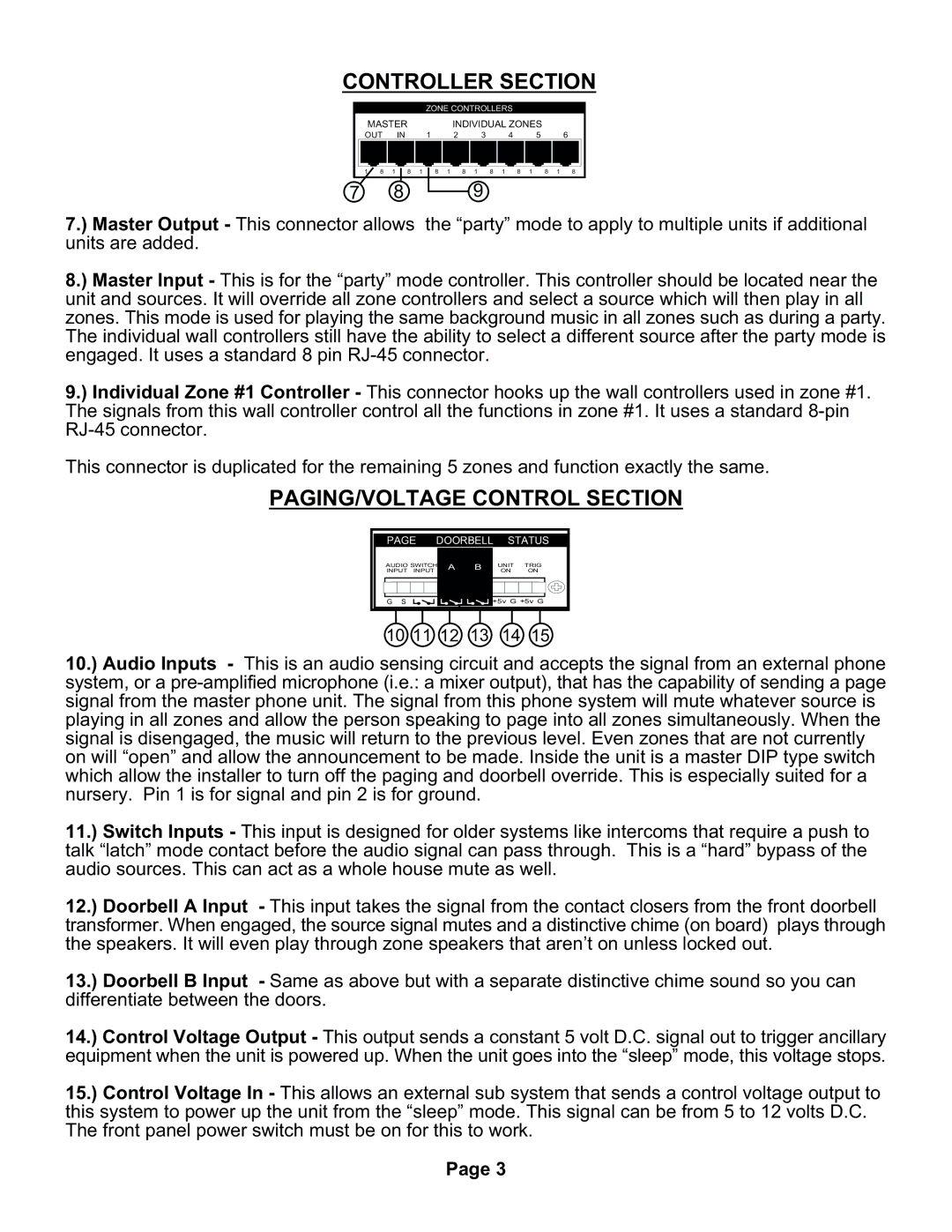
7.) Master Output - This connector allows |
| the “party” mode to apply to multiple units if additional | ||||||||||||||||||||||||
units are added. |
|
|
|
|
|
|
|
|
|
|
|
|
|
|
|
|
|
|
|
|
|
|
|
|
| |
8.) Master Input - This is for the “party” mode controller. This controller should be located near the unit and sources. It will override all zone controllers and select a source which will then play in all zones. This mode is used for playing the same background music in all zones such as during a party. The individual wall controllers still have the ability to select a different source after the party mode is engaged. It uses a standard 8 pin
9.) Individual Zone #1 Controller - This connector hooks up the wall controllers used in zone #1. The signals from this wall controller control all the functions in zone #1. It uses a standard
This connector is duplicated for the remaining 5 zones and function exactly the same.
PAGING/VOLTAGE CONTROL SECTION
PAGE | DOORBELL | STATUS | |||
AUDIO SWITCH | A | B | UNIT | TRIG | |
INPUT INPUT |
| ON | ON | ||
|
|
| |||
GS GS |
|
| +5v G +5v G | ||
10 11 12 13 14 15
10.) Audio Inputs - This is an audio sensing circuit and accepts the signal from an external phone system, or a
11.) Switch Inputs - This input is designed for older systems like intercoms that require a push to talk “latch” mode contact before the audio signal can pass through. This is a “hard” bypass of the audio sources. This can act as a whole house mute as well.
12.) Doorbell A Input - This input takes the signal from the contact closers from the front doorbell transformer. When engaged, the source signal mutes and a distinctive chime (on board) plays through the speakers. It will even play through zone speakers that aren’t on unless locked out.
13.) Doorbell B Input - Same as above but with a separate distinctive chime sound so you can differentiate between the doors.
14.) Control Voltage Output - This output sends a constant 5 volt D.C. signal out to trigger ancillary equipment when the unit is powered up. When the unit goes into the “sleep” mode, this voltage stops.
15.) Control Voltage In - This allows an external sub system that sends a control voltage output to this system to power up the unit from the “sleep” mode. This signal can be from 5 to 12 volts D.C. The front panel power switch must be on for this to work.
Page 3