WOODBURNER specifications
The Charnwood Woodburner is a highly regarded heating solution, renowned for its blend of pioneering technology, efficiency, and elegant design. Perfectly suited for modern homes, the Woodburner offers warmth and ambiance while minimizing environmental impact.One of the main features of the Charnwood Woodburner is its impressive efficiency rating. With high thermal efficiency often exceeding 80%, it maximizes the heat generated from each log, reducing the amount of fuel needed and ensuring that your home remains cozy and warm even in the depths of winter. This efficiency is largely thanks to its advanced air wash system, which helps keep the glass door clear of soot, providing an unobstructed view of the flame while maintaining an aesthetically pleasing look.
The Charnwood Woodburner employs a clever combustion system designed to optimize fuel burning. This multi-fuel capability allows users to burn both wood and smokeless fuels, providing versatility to accommodate various preferences and regional regulations. Its primary and secondary air inlets ensure that fuel burns at the optimal rate, resulting in cleaner emissions and less environmental impact.
In terms of design, the Charnwood Woodburner achieves a perfect blend of style and functionality. It comes in various models and finishes, allowing homeowners to choose one that complements their interiors. The range includes contemporary and traditional styles, catering to diverse tastes and preferences.
Another commendable characteristic of the Charnwood Woodburner is its build quality. Crafted from robust cast iron and high-quality steel, it is designed for longevity and durability. This rugged construction not only enhances the stove's performance but also contributes to its classic aesthetic appeal.
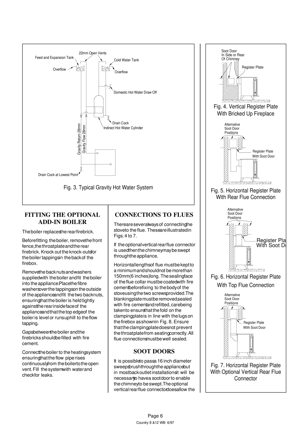
Additionally, the Woodburner is equipped with a convenient top or rear flue exit, providing flexibility in installation, making it adaptable for different room layouts.
Overall, the Charnwood Woodburner encapsulates efficiency, stylish design, and environmental responsibility, making it a premier choice for anyone looking to embrace the warmth and comfort of a wood-burning stove without compromising on modern standards. With the Charnwood Woodburner, you won't just heat your home; you'll create a welcoming atmosphere that resonates with the charm of a traditional fireplace while enjoying the convenience of contemporary technology.

