DMX Primer
The USITT
In addition, there can only be one DMX controller operating on the same DMX connection at any given time. Otherwise, the signals from one controller could interfere with the signals from the other controller, thus causing erratic fixture operation.
Starting Address
Once the user has determined how many channels each fixture requires, he or she must assign the corresponding channels on the DMX controller for it to send the control signals to the intended fixture. In the DMX system, each fixture is identified by its starting address. The starting address is the number of the DMX channel assigned to the first control channel on the fixture.
For instance, a user has two DMX compatible fixtures. One of them has four channels and the other has six channels. The user may configure the starting address of the
Choosing a starting address should be planned carefully. The first requirement is to avoid channel overlapping. Doing otherwise may result in erratic operation of the affected fixtures. The second requirement is to avoid leaving unassigned channels because this creates unused faders on the DMX controller, which may be critical for small DMX controllers with only a few available faders.
It is possible to control multiple fixtures of the same type by assigning each one of them the same starting address. In this case, all the fixtures would respond in unison (synchronized) to the signals from the DMX controller.
Fixture Linking (Daisy Chain)
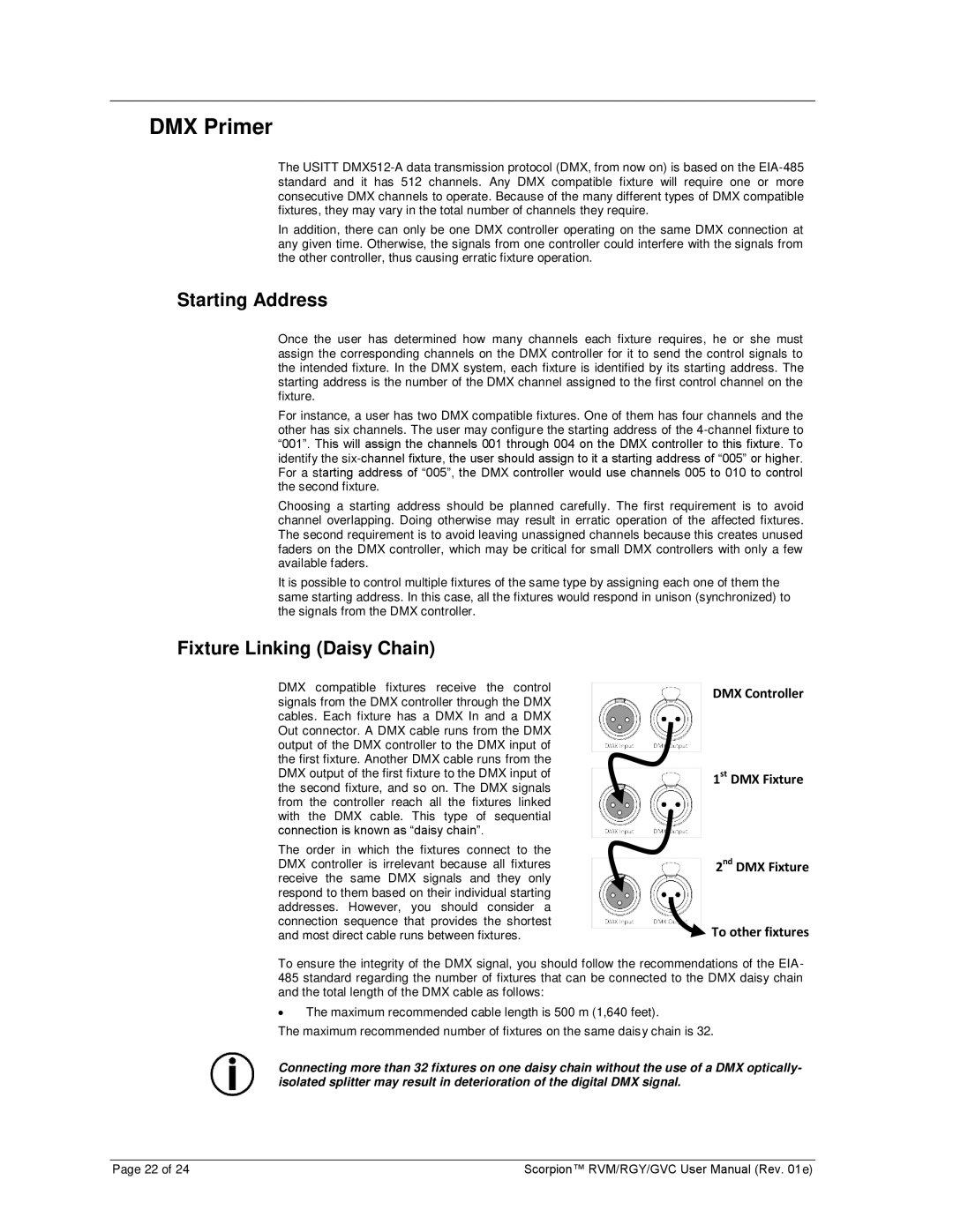
DMX compatible fixtures receive the control signals from the DMX controller through the DMX cables. Each fixture has a DMX In and a DMX Out connector. A DMX cable runs from the DMX output of the DMX controller to the DMX input of the first fixture. Another DMX cable runs from the DMX output of the first fixture to the DMX input of the second fixture, and so on. The DMX signals from the controller reach all the fixtures linked with the DMX cable. This type of sequential connection is known as “daisy chain”.
The order in which the fixtures connect to the DMX controller is irrelevant because all fixtures receive the same DMX signals and they only respond to them based on their individual starting addresses. However, you should consider a connection sequence that provides the shortest and most direct cable runs between fixtures.
DMX Controller
1st DMX Fixture
2nd DMX Fixture
To other fixtures
To ensure the integrity of the DMX signal, you should follow the recommendations of the EIA- 485 standard regarding the number of fixtures that can be connected to the DMX daisy chain and the total length of the DMX cable as follows:
∙The maximum recommended cable length is 500 m (1,640 feet).
The maximum recommended number of fixtures on the same daisy chain is 32.
Connecting more than 32 fixtures on one daisy chain without the use of a DMX optically- isolated splitter may result in deterioration of the digital DMX signal.
Page 22 of 24 | Scorpion™ RVM/RGY/GVC User Manual (Rev. 01e) |
