6159939130 CS7000 Controller Hardware Overview Manual
| Table | ||
|
|
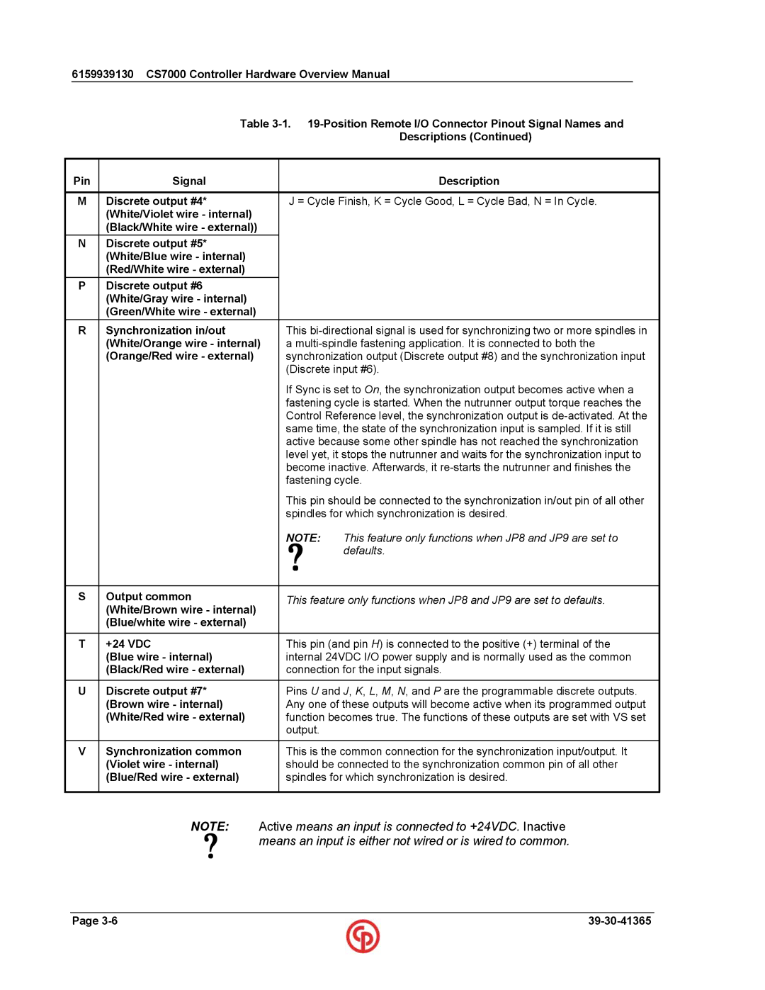
| Descriptions (Continued) |
|
|
|
|
Pin | Signal |
| Description |
|
|
| |
M | Discrete output #4* | J = Cycle Finish, K = Cycle Good, L = Cycle Bad, N = In Cycle. | |
| (White/Violet wire - internal) |
|
|
| (Black/White wire - external)) |
|
|
N | Discrete output #5* |
|
|
| (White/Blue wire - internal) |
|
|
| (Red/White wire - external) |
|
|
P | Discrete output #6 |
|
|
| (White/Gray wire - internal) |
|
|
| (Green/White wire - external) |
|
|
|
|
| |
R | Synchronization in/out | This | |
| (White/Orange wire - internal) | a | |
| (Orange/Red wire - external) | synchronization output (Discrete output #8) and the synchronization input | |
|
| (Discrete input #6). | |
|
| If Sync is set to On, the synchronization output becomes active when a | |
|
| fastening cycle is started. When the nutrunner output torque reaches the | |
|
| Control Reference level, the synchronization output is | |
|
| same time, the state of the synchronization input is sampled. If it is still | |
|
| active because some other spindle has not reached the synchronization | |
|
| level yet, it stops the nutrunner and waits for the synchronization input to | |
|
| become inactive. Afterwards, it | |
|
| fastening cycle. | |
|
| This pin should be connected to the synchronization in/out pin of all other | |
|
| spindles for which synchronization is desired. | |
|
| ? | This feature only functions when JP8 and JP9 are set to |
|
| NOTE: | |
|
|
| defaults. |
|
|
|
|
S | Output common | This feature only functions when JP8 and JP9 are set to defaults. | |
| (White/Brown wire - internal) | ||
|
|
| |
| (Blue/white wire - external) |
|
|
|
|
| |
T | +24 VDC | This pin (and pin H) is connected to the positive (+) terminal of the | |
| (Blue wire - internal) | internal 24VDC I/O power supply and is normally used as the common | |
| (Black/Red wire - external) | connection for the input signals. | |
|
|
| |
U | Discrete output #7* | Pins U and J, K, L, M, N, and P are the programmable discrete outputs. | |
| (Brown wire - internal) | Any one of these outputs will become active when its programmed output | |
| (White/Red wire - external) | function becomes true. The functions of these outputs are set with VS set | |
|
| output. |
|
|
|
| |
V | Synchronization common | This is the common connection for the synchronization input/output. It | |
| (Violet wire - internal) | should be connected to the synchronization common pin of all other | |
| (Blue/Red wire - external) | spindles for which synchronization is desired. | |
|
|
|
|
NOTE: | Active means an input is connected to +24VDC. Inactive |
? | means an input is either not wired or is wired to common. |
|
Page |