Chapter 3. Installing the CS7000 Controller
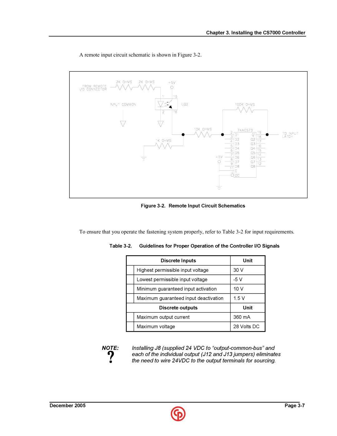
A remote input circuit schematic is shown in Figure
Figure 3-2. Remote Input Circuit Schematics
To ensure that you operate the fastening system properly, refer to Table
Table
| Discrete Inputs |
| Unit |
|
|
|
|
| Highest permissible input voltage | 30 | V |
|
|
| |
| Lowest permissible input voltage | ||
|
|
|
|
| Minimum guaranteed input activation | 10 | V |
|
|
| |
| Maximum guaranteed input deactivation | 1.5 V | |
|
|
|
|
| Discrete outputs |
| Unit |
|
|
| |
| Maximum output current | 360 mA | |
|
|
|
|
| Maximum voltage | 28 | Volts DC |
|
|
|
|
NOTE: Installing J8 (supplied 24 VDC to
the need to wire 24VDC to the output terminals for sourcing.
____________________________________________________________________________________________
December 2005 | Page |