
KSY220 specifications
Chief Manufacturing has made a significant impact in the realm of display mounting solutions, and one of its standout products is the KSY220. This innovative mount exemplifies the company’s commitment to quality, durability, and ease of use, catering to the needs of both commercial and residential applications.The KSY220 is designed primarily for large format displays, supporting screens ranging from 40 to 80 inches in size. One of its main features is the sturdy construction, utilizing high-grade materials that ensure long-lasting performance and stability. This robust design allows the mount to accommodate a substantial weight capacity, with the ability to hold displays up to 200 pounds securely.
One of the distinguishing characteristics of the KSY220 is its versatility. The mount offers tilt, swivel, and extension capabilities, enabling users to customize their display positioning to achieve optimal viewing angles. The tilt feature allows for a +15° to -5° adjustment, making it easier to reduce glare and improve visibility, especially in settings where lighting conditions may vary. The full-motion design also facilitates side-to-side movement, enhancing accessibility for screen adjustments.
Installation of the KSY220 is streamlined, thanks to its user-friendly design. The mount comes with all necessary hardware and an installation guide to help users get set up quickly and efficiently. Its universal VESA compatibility means it can fit a wide range of display brands, making it a flexible solution for various environments.
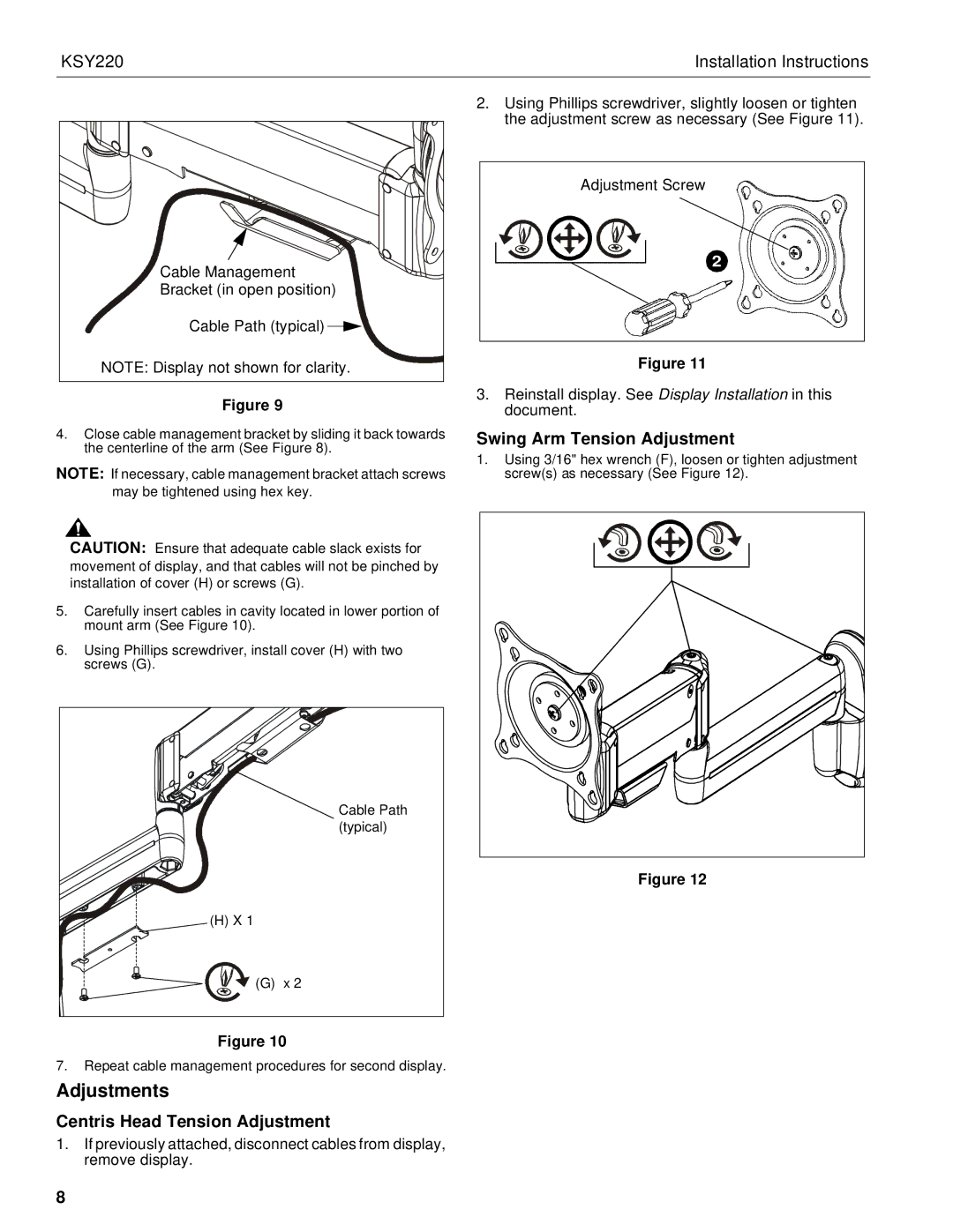
In terms of technology, the KSY220 incorporates advanced cable management systems, which help maintain a clean and organized appearance by concealing cables and wires. This not only enhances aesthetics but also reduces potential hazards associated with exposed cords.
Overall, the Chief Manufacturing KSY220 standing mount is an excellent choice for those seeking a balance of functionality and style. Its durable construction, versatile positioning options, and efficient cable management make it ideal for both professional and home use. With the KSY220, users can expect a reliable solution that elevates their display experience while ensuring safety and convenience.