Installation Instructions | MIWRF SERIES |
WARNING: ELECTRICAL SHOCK HAZARD! CUTTING OR DRILLING INTO ELECTRICAL WIRES OR CABLES CAN CAUSE DEATH OR SERIOUS PERSONAL INJURY! ALWAYS make certain area behind mounting surfaces is free of electrical wires and cables before cutting, drilling, or installing fasteners.
WARNING: EXPLOSION AND FIRE HAZARD! CUTTING OR DRILLING INTO GAS PLUMBING CAN CAUSE DEATH OR SERIOUS PERSONAL INJURY! ALWAYS make certain area behind mounting surfaces is free of gas, water, waste, or any other plumbing before cutting, drilling, or installing fasteners.
5.Cut drywall on outside edge of lines and remove.
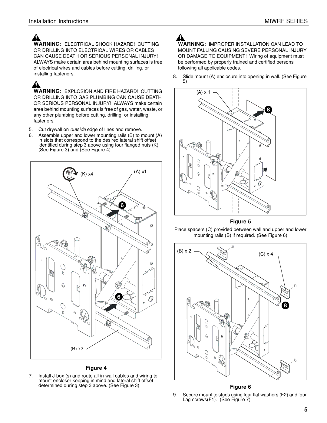
6.Assemble upper and lower mounting rails (B) to mount (A) in slots that correspond to the desired lateral shift offset identified during step 3 above using four flanged nuts (K). (See Figure 3) and (See Figure 4)
(K) x4 | (A) x1 |
| |
| 6 |
| 6 |
(B) x2 |
|
Figure 4
7.Install
WARNING: IMPROPER INSTALLATION CAN LEAD TO MOUNT FALLING CAUSING SEVERE PERSONAL INJURY OR DAMAGE TO EQUIPMENT! Wiring of equipment must be performed by properly trained and certified persons following all applicable codes.
8.Slide mount (A) enclosure into opening in wall. (See Figure 5)
(A) x 1 |
8 |
Figure 5
Place spacers (C) provided between wall and upper and lower
mounting rails (B) if required. (See Figure 6)
(B) x 2 | (C) x 4 |
| |
| 8 |
Figure 6
9.Secure mount to studs using four flat washers (F2) and four Lag screws(F1). (See Figure 7)
5
