MIWRF SERIES | Installation Instructions |
Installation
WARNING: IMPROPER INSTALLATION CAN RESULT IN DEATH OR SERIOUS PERSONAL INJURY! This accessory should be installed by qualified personnel only.
WARNING: IMPROPER INSTALLATION CAN LEAD TO MOUNT FALLING CAUSING SEVERE PERSONAL INJURY OR DAMAGE TO EQUIPMENT! DO NOT deviate from installation instructions provided. DO NOT substitute hardware.
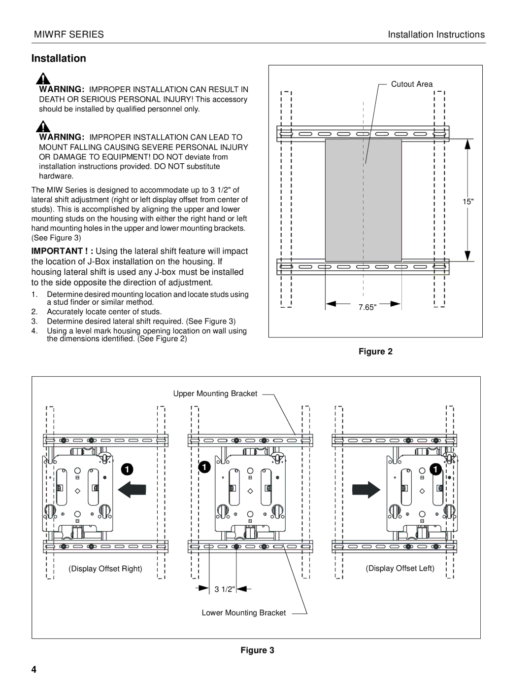
The MIW Series is designed to accommodate up to 3 1/2" of lateral shift adjustment (right or left display offset from center of studs). This is accomplished by aligning the upper and lower mounting studs on the housing with either the right hand or left hand mounting holes in the upper and lower mounting brackets. (See Figure 3)
IMPORTANT ! : Using the lateral shift feature will impact the location of
1.Determine desired mounting location and locate studs using a stud finder or similar method.
2.Accurately locate center of studs.
3.Determine desired lateral shift required. (See Figure 3)
4.Using a level mark housing opening location on wall using the dimensions identified. (See Figure 2)
Cutout Area |
15" |
7.65" |
Figure 2
| Upper Mounting Bracket |
|
1 | 1 | 1 |
(Display Offset Right) |
| (Display Offset Left) |
| 3 1/2" |
|
| Lower Mounting Bracket |
|
Figure 3
4