MIWRF SERIES | Installation Instructions |
CABLE MANAGEMENT
WARNING: IMPROPER INSTALLATION CAN LEAD TO SERIOUS PERSONAL INJURY OR DAMAGE TO EQUIPMENT! Make sure cables do not run through pinch points.
1.Locate and install cable tie clips (J) where desired for proper cable routing. (See Figure 12)
1 |
(J) x 8 |
Figure 12
2.Route cables down arms on mount. (See Figure 13)
3.Position cable covers (L) over arm and cable and press cable covers (L) down on to arms to secure cables. (See Figure 13)
WARNING: IMPROPER INSTALLATION CAN LEAD TO SERIOUS PERSONAL INJURY OR DAMAGE TO EQUIPMENT! DO NOT route cables through holes in
faceplate. |
2 |
3 |
(L) x 4 |
From Display |
Figure 13
ADJUSTMENTS
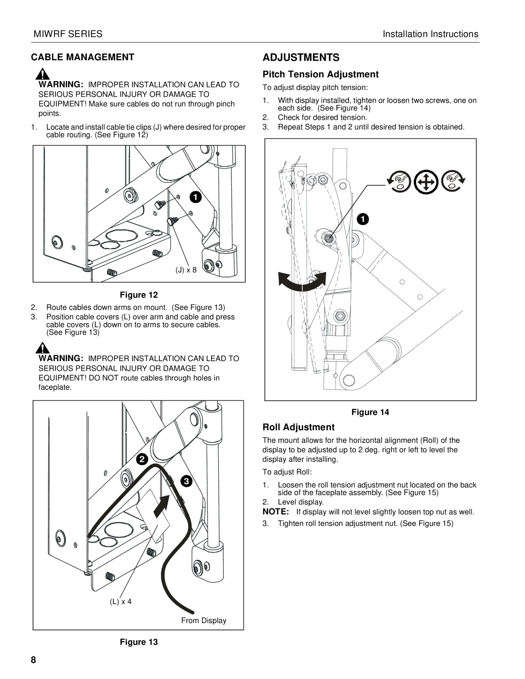
Pitch Tension Adjustment
To adjust display pitch tension:
1.With display installed, tighten or loosen two screws, one on each side. (See Figure 14)
2.Check for desired tension.
3.Repeat Steps 1 and 2 until desired tension is obtained.
1 |
Figure 14
Roll Adjustment
The mount allows for the horizontal alignment (Roll) of the display to be adjusted up to 2 deg. right or left to level the display after installing.
To adjust Roll:
1.Loosen the roll tension adjustment nut located on the back side of the faceplate assembly. (See Figure 15)
2.Level display.
NOTE: If display will not level slightly loosen top nut as well.
3.Tighten roll tension adjustment nut. (See Figure 15)
8