Installation Instructions | MIWRF SERIES |
Trim Installation
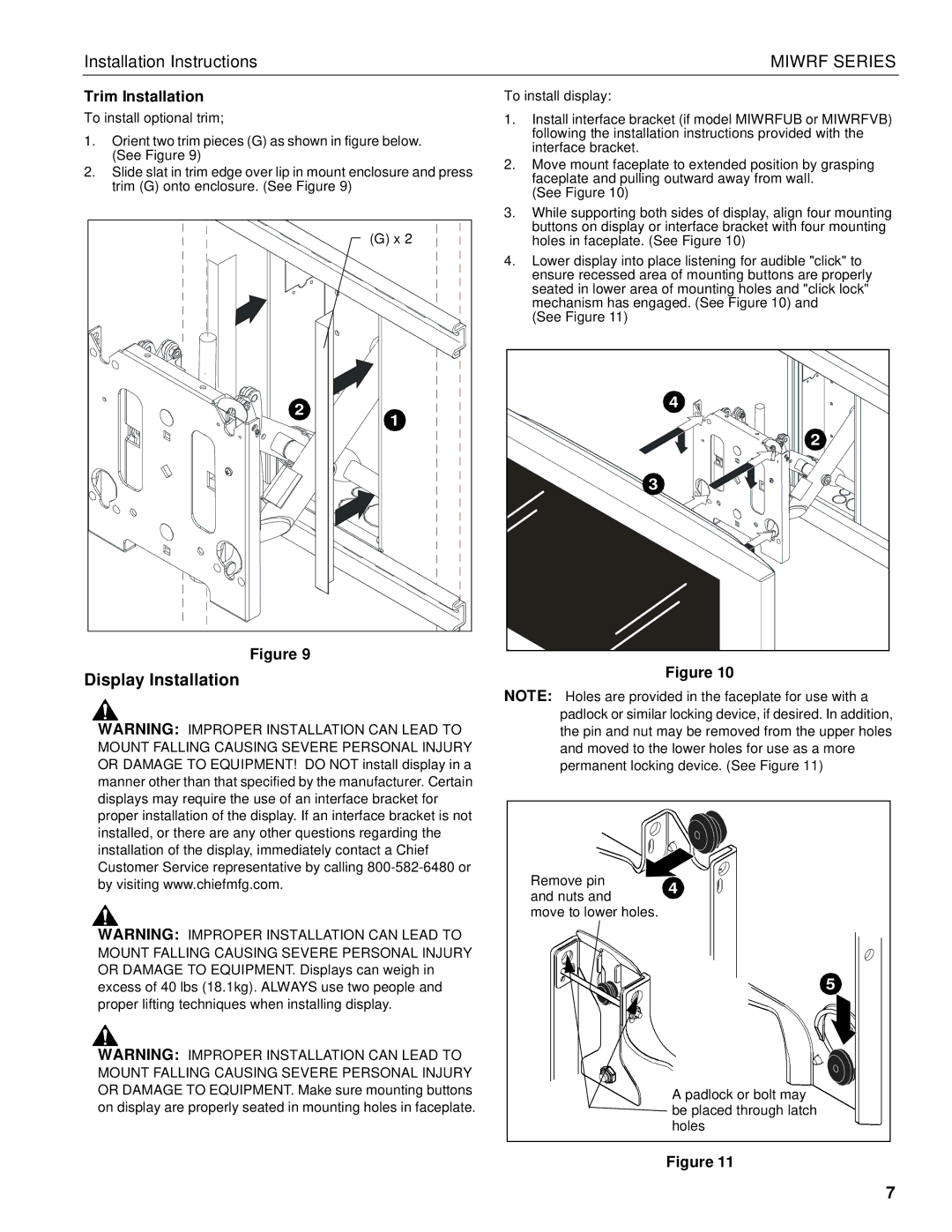
To install optional trim;
1.Orient two trim pieces (G) as shown in figure below. (See Figure 9)
2.Slide slat in trim edge over lip in mount enclosure and press trim (G) onto enclosure. (See Figure 9)
(G) x 2 |
2 |
1 |
Figure 9
Display Installation
WARNING: IMPROPER INSTALLATION CAN LEAD TO MOUNT FALLING CAUSING SEVERE PERSONAL INJURY OR DAMAGE TO EQUIPMENT! DO NOT install display in a manner other than that specified by the manufacturer. Certain displays may require the use of an interface bracket for proper installation of the display. If an interface bracket is not installed, or there are any other questions regarding the installation of the display, immediately contact a Chief Customer Service representative by calling
WARNING: IMPROPER INSTALLATION CAN LEAD TO MOUNT FALLING CAUSING SEVERE PERSONAL INJURY OR DAMAGE TO EQUIPMENT. Displays can weigh in excess of 40 lbs (18.1kg). ALWAYS use two people and proper lifting techniques when installing display.
WARNING: IMPROPER INSTALLATION CAN LEAD TO MOUNT FALLING CAUSING SEVERE PERSONAL INJURY OR DAMAGE TO EQUIPMENT. Make sure mounting buttons on display are properly seated in mounting holes in faceplate.
To install display:
1.Install interface bracket (if model MIWRFUB or MIWRFVB) following the installation instructions provided with the interface bracket.
2.Move mount faceplate to extended position by grasping faceplate and pulling outward away from wall.
(See Figure 10)
3.While supporting both sides of display, align four mounting buttons on display or interface bracket with four mounting holes in faceplate. (See Figure 10)
4.Lower display into place listening for audible "click" to ensure recessed area of mounting buttons are properly seated in lower area of mounting holes and "click lock" mechanism has engaged. (See Figure 10) and
(See Figure 11)
4 |
2 |
3 |
Figure 10
NOTE: Holes are provided in the faceplate for use with a padlock or similar locking device, if desired. In addition, the pin and nut may be removed from the upper holes and moved to the lower holes for use as a more permanent locking device. (See Figure 11)
Remove pin | 4 | |
and nuts and | ||
| ||
move to lower holes. |
| |
| 5 | |
| A padlock or bolt may | |
| be placed through latch | |
| holes |
Figure 11
7