PNR specifications
Chief Manufacturing PNR, a leading innovator in the audiovisual mounting and display solutions sector, has positioned itself as a pivotal player for professionals in diverse industries, from corporate environments to educational institutions. With an unwavering commitment to quality and functionality, Chief continually enhances its product offerings to meet the evolving needs of a dynamic market.One of the standout features of Chief Manufacturing PNR is its robust construction. The mounts are made from high-quality materials ensuring durability and long-lasting performance. This resilience is crucial for environments where equipment is frequently adjusted or subjected to heavy usage, thus ensuring stable support for various display sizes.
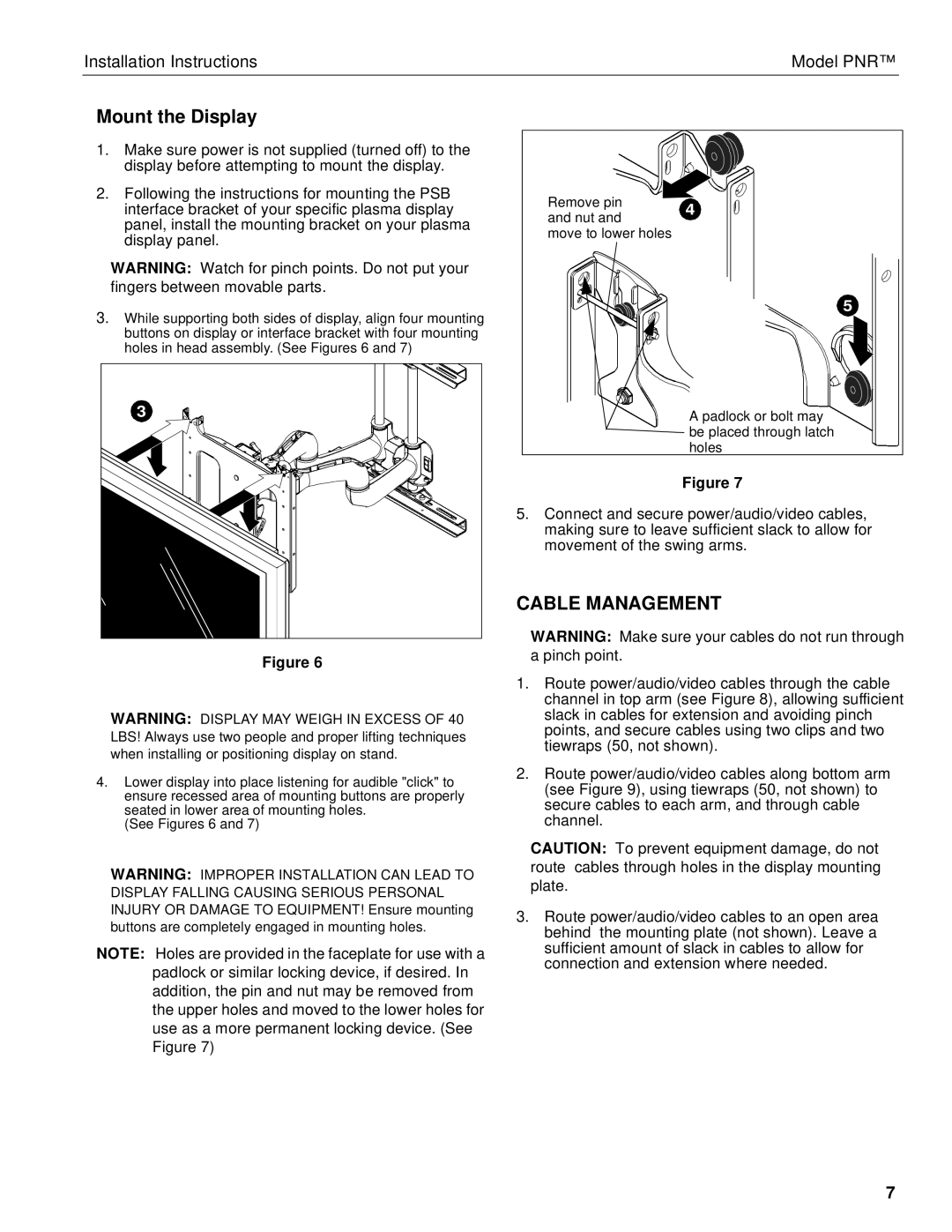
Technologically, Chief Manufacturing PNR integrates advanced installation and adjustment features. The innovative design includes tools such as Quick Connect and Easy Connect systems, simplifying the mounting process for installers. These systems allow for fast adjustments, making it easy to align displays accurately and ensure that they are secure and stable. Additionally, many of the mounts are equipped with cable management solutions to keep installations neat and organized, promoting a professional appearance and reducing clutter.
The flexibility of the Chief PNR series is another noteworthy characteristic. The mounts offer a range of adjustments including tilt, pan, and swivel capabilities. These features allow users to optimize the viewing experience in any space, adapting to different angles and placements, which is particularly beneficial for conference rooms, classrooms, and other multi-use environments.
Moreover, Chief Manufacturing places a strong emphasis on compatibility with various displays, encompassing a broad spectrum of sizes and brands. This level of versatility ensures that customers can confidently select a PNR mount for their specific application.
With a focus on ergonomic principles, Chief designs its products to enhance user experience, ensuring that displays are positioned at optimal viewing heights to reduce eye strain and enhance engagement.
In summary, Chief Manufacturing PNR represents the fusion of quality construction, innovative technology, and user-focused design. Its offerings not only facilitate easy installation and adjustability but also cater to a wide range of audiovisual needs, reinforcing Chief’s commitment to delivering excellence in the mounting solutions industry. As the audiovisual landscape evolves, Chief continues to be at the forefront, ensuring that its products meet the demands of modern enterprises and environments.

