Chapter 1 Concepts
Views
You may or may not see all of these views using this EM (exceptions noted). These views all exist within EMs, however they are not all implemented. If multiple EMs are
As the following sections detail, the views you will use to perform the majority of the EM capabilities are the Physical and Component Managed views. Both are similar in structure and allow you to initiate the EM windows. However it is recommended that you use the Physical view to perform most management functions within the EM. The Physical view provides a graphical representation of the chassis that the Component Managed view does not. It should, however, be noted that you must use the Component Managed view to see representative ATM connection objects within the EM as ATM connection objects are not available through the Physical view.
Component Managed View
The Component Managed view displays all objects within the Cisco EMF system. For example, say you have two different EMs installed in Cisco EMF: EM A and EM B. Information for both the EM A and EM B display within the Component Managed view. Additionally, the Component Managed view also displays ATM connections such as PVCs and SPVCs. Connection objects are not visible in any other view. However, it is not recommended to work within this view unless you have multiple EMs installed.
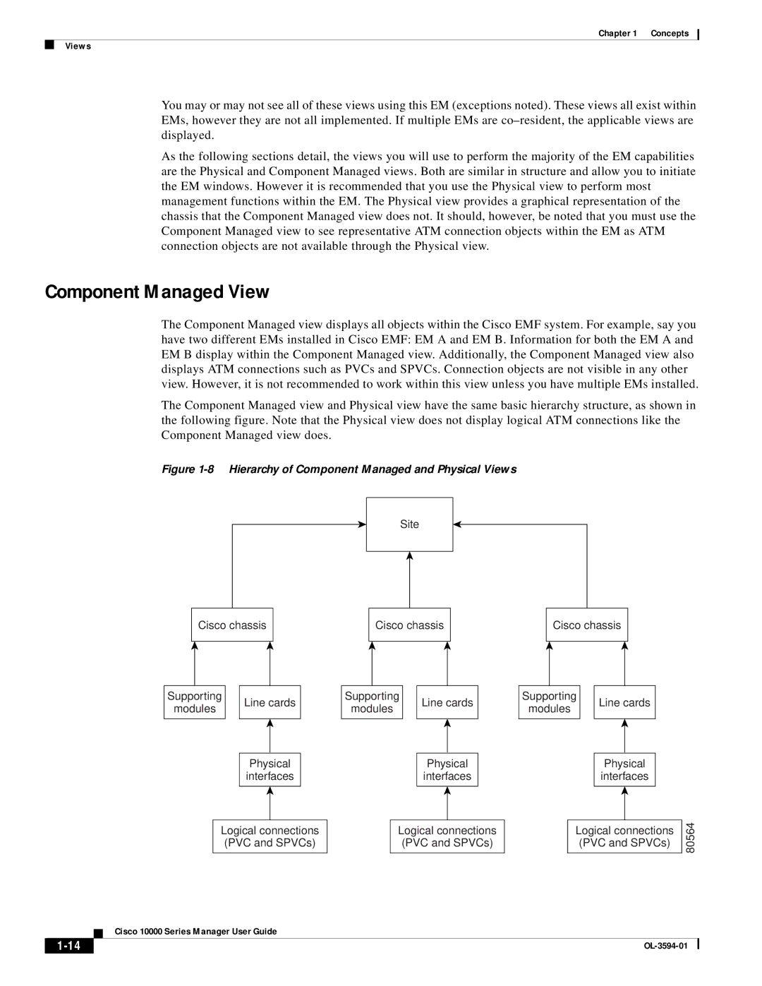
The Component Managed view and Physical view have the same basic hierarchy structure, as shown in the following figure. Note that the Physical view does not display logical ATM connections like the Component Managed view does.
Figure 1-8 Hierarchy of Component Managed and Physical Views
Site
Cisco chassis
Cisco chassis
Cisco chassis
Supporting
modules
Line cards
Physical
interfaces
Supporting
modules
Line cards
Physical
interfaces
Supporting
modules
Line cards
Physical
interfaces
Logical connections (PVC and SPVCs)
Logical connections (PVC and SPVCs)
Logical connections (PVC and SPVCs)
80564
Cisco 10000 Series Manager User Guide
| ||
|
