Chapter 1 Concepts
EM Objects and Interfaces
Physical Objects
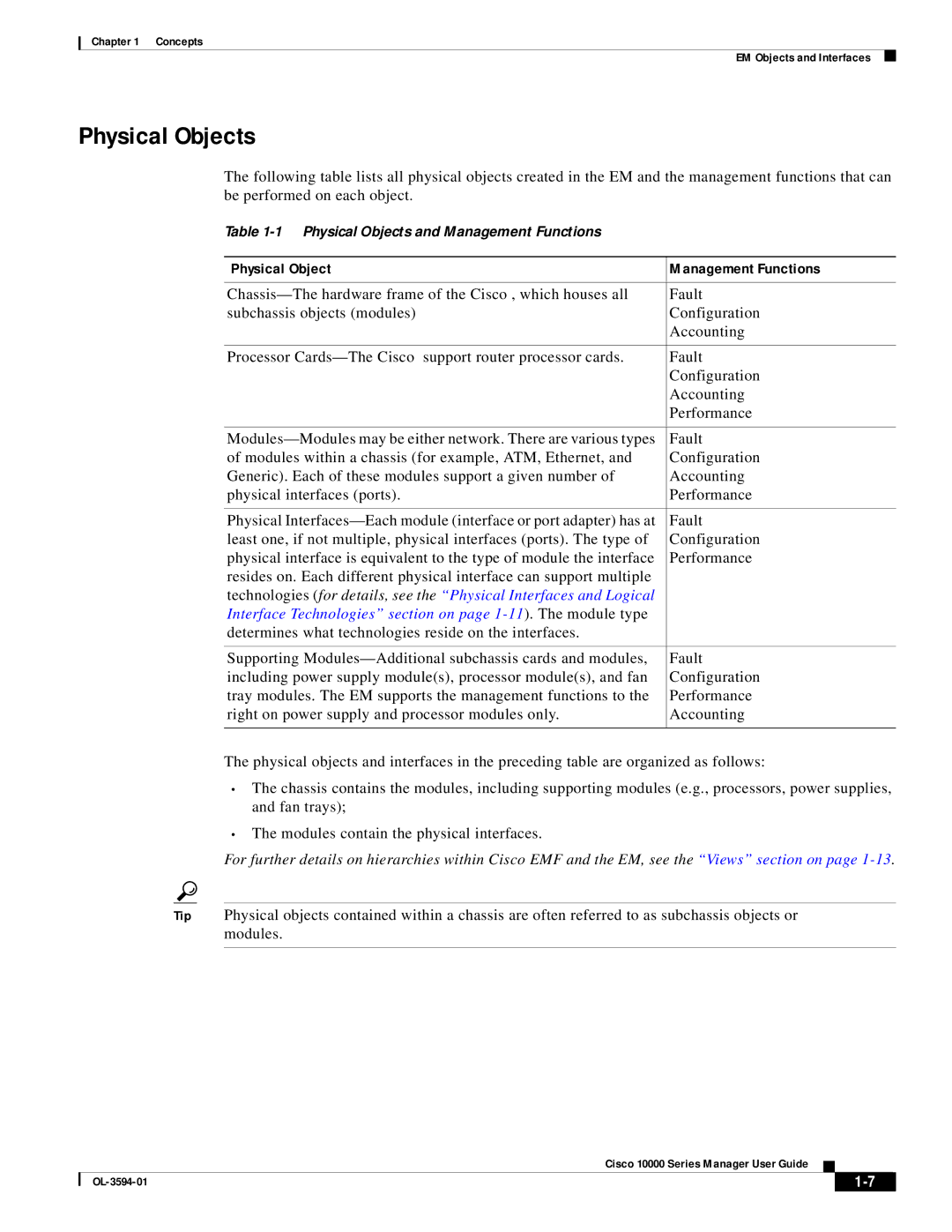
The following table lists all physical objects created in the EM and the management functions that can be performed on each object.
Table
Physical Object | Management Functions |
|
|
Fault | |
subchassis objects (modules) | Configuration |
| Accounting |
|
|
Processor | Fault |
| Configuration |
| Accounting |
| Performance |
|
|
Fault | |
of modules within a chassis (for example, ATM, Ethernet, and | Configuration |
Generic). Each of these modules support a given number of | Accounting |
physical interfaces (ports). | Performance |
|
|
Physical | Fault |
least one, if not multiple, physical interfaces (ports). The type of | Configuration |
physical interface is equivalent to the type of module the interface | Performance |
resides on. Each different physical interface can support multiple |
|
technologies (for details, see the “Physical Interfaces and Logical |
|
Interface Technologies” section on page |
|
determines what technologies reside on the interfaces. |
|
|
|
Supporting | Fault |
including power supply module(s), processor module(s), and fan | Configuration |
tray modules. The EM supports the management functions to the | Performance |
right on power supply and processor modules only. | Accounting |
|
|
The physical objects and interfaces in the preceding table are organized as follows:
•The chassis contains the modules, including supporting modules (e.g., processors, power supplies, and fan trays);
•The modules contain the physical interfaces.
For further details on hierarchies within Cisco EMF and the EM, see the “Views” section on page
Tip Physical objects contained within a chassis are often referred to as subchassis objects or modules.
Cisco 10000 Series Manager User Guide
|
| ||
|
|
