Chapter 8 Installing and Upgrading Internal Modules in Cisco 1805 Cable Routers
Modules Internal to the Cisco 1805 Cable Router
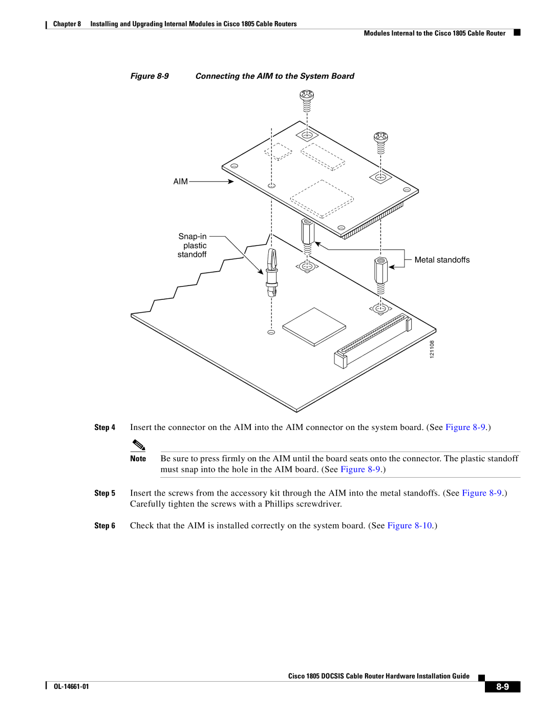
Figure 8-9 Connecting the AIM to the System Board
AIM
standoff
![]()
![]() Metal standoffs
Metal standoffs
121108
Step 4 Insert the connector on the AIM into the AIM connector on the system board. (See Figure
Note Be sure to press firmly on the AIM until the board seats onto the connector. The plastic standoff must snap into the hole in the AIM board. (See Figure
Step 5 Insert the screws from the accessory kit through the AIM into the metal standoffs. (See Figure
Step 6 Check that the AIM is installed correctly on the system board. (See Figure
Cisco 1805 DOCSIS Cable Router Hardware Installation Guide
|
| ||
|
|