Chapter 8 Installing and Upgrading Internal Modules in Cisco 1805 Cable Routers
Modules Internal to the Cisco 1805 Cable Router
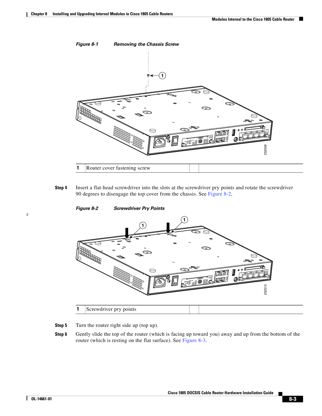
Figure 8-1 Removing the Chassis Screw
1
1
|
|
|
|
|
| KN L x2 R WP | KNL x 3 | RW | P |
|
|
|
| KNL | x1 RWP |
|
| W SE4 | |
|
| KNL x0 | RWP |
|
|
| ICWH | ||
|
|
|
|
|
|
| |||
|
| CAB |
|
|
|
|
|
|
|
| LEBAC |
|
|
|
|
|
|
| |
|
|
|
|
|
|
|
| ||
| ONLINE |
|
|
|
|
|
|
|
|
ER WPO | US |
|
|
|
|
|
|
|
|
LINK | SD |
|
|
|
|
|
|
|
|
|
|
|
|
|
|
|
| 232509 | |
Router cover fastening screw
Step 4 Insert a
Figure 8-2 Screwdriver Pry Points
g
1
1
1
|
| LNK 2x PWR | LNK | 3x | PWR |
| LNK 1x PWR |
|
| 4ESW | |
LNK 0x PWR |
|
|
| CHWI | |
|
|
|
|
|
| CABLE | |
| CABLE | ||
|
| ||
WERPO | ONLINE |
|
|
US |
|
| |
LINK | DS |
| 232513 |
|
|
|
Screwdriver pry points
Step 5 Turn the router right side up (top up).
Step 6 Gently slide the top of the router (which is facing up toward you) away and up from the bottom of the router (which is resting on the flat surface). See Figure
Cisco 1805 DOCSIS Cable Router Hardware Installation Guide
|
| ||
|
|