Chapter 8 Installing and Upgrading Internal Modules in Cisco 1805 Cable Routers
Modules Internal to the Cisco 1805 Cable Router
Caution When you install an AIM, always wear an
Caution Handle AIMs by the edges only. AIMs are
Accessory Kit to Use
Some AIMs are provided with multiple accessory kits that contain different configurations of mounting hardware. Mounting hardware for the Cisco 1805 cable router consists of two machine thread metal standoffs, two machine thread metal screws, and one plastic standoff.
To install an AIM module on the Cisco 1805 cable router, use the hardware in mounting kit
Installation Procedure
To install the AIM, perform the following steps. You need a number 2 Phillips screwdriver or
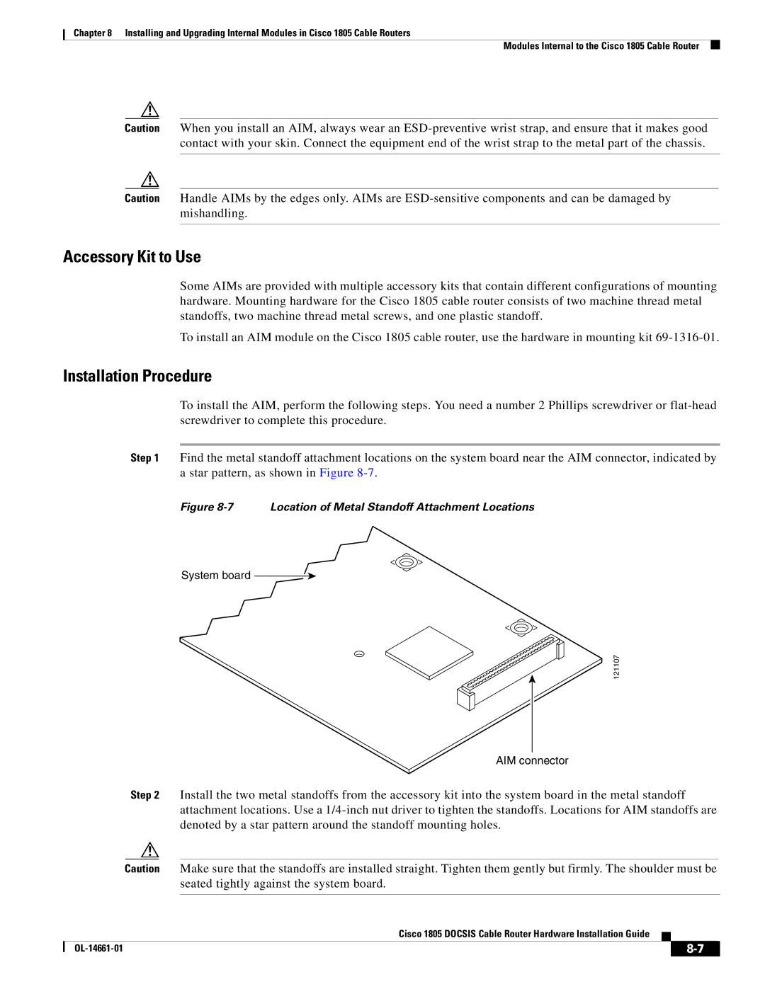
Step 1 Find the metal standoff attachment locations on the system board near the AIM connector, indicated by a star pattern, as shown in Figure
Figure 8-7 Location of Metal Standoff Attachment Locations
System board ![]()
121107
AIM connector
Step 2 Install the two metal standoffs from the accessory kit into the system board in the metal standoff attachment locations. Use a
Caution Make sure that the standoffs are installed straight. Tighten them gently but firmly. The shoulder must be seated tightly against the system board.
Cisco 1805 DOCSIS Cable Router Hardware Installation Guide
|
| ||
|
|