Manuals
/
Cisco Systems
/
Computer Equipment
/
Switch
Cisco Systems
4490
appendix
Connecting Cables, 3-14
Models:
4490
1
14
20
20
Download
20 pages
33.28 Kb
11
12
13
14
15
16
17
18
Install
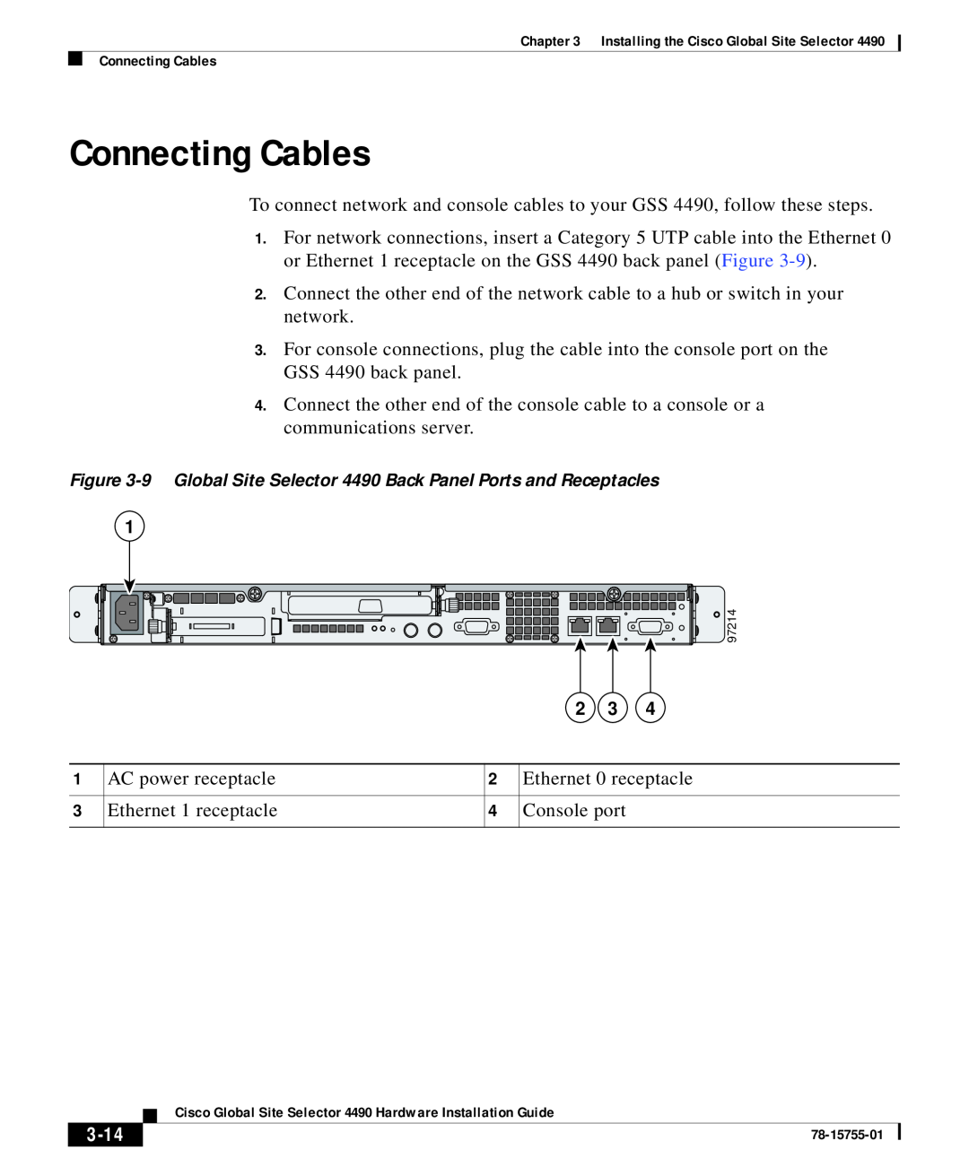
Connecting Cables
Slide rail assembly
Adjustment screw
Connecting Power
Page 14
Image 14
Page 13
Page 15
Page 14
Image 14
Page 13
Page 15
Contents
Installing the Cisco Global Site Selector
C H A P T E R
Cisco Global Site Selector Hardware Installation Guide
Unpacking and Inspecting the Global Site Selector
Tools and Parts Required
If the Product is Damaged
Figure 3-1 Four-Post Rack Installation Kit
83198
Installing Your Unit
Installing the Chassis in a Four-Post Rack
Figure 3-2 Installing Clip Nuts or Cage Nuts in a Non-Threaded Rack
Slide rail assembly
Figure 3-4 Attaching the Inner Slide Rail to the GSS
2 Adjustment screw
3-10
Release tab
Cisco Global Site Selector 4490 Hardware Installation Guide
3-11
Installing the Chassis in a Two-Post Rack
Chapter 3 Installing the Cisco Global Site Selector
3-12
Repeat this step to secure the left side bracket to the rack
Installing the Chassis on a Workbench or Tabletop
3-13
Connecting Cables
3-14
3-15
Connecting Power
Booting the System
Color
Checking the Front Panel LEDs
3-16
State
Table 3-1 Front Panel LEDs continued
Removing or Replacing a Cisco Global Site Selector
3-17
3-18
To physically remove a GSS 4490 from your network, follow these steps
3-19
To physically replace a GSS 4490, follow these steps
3-20
Top
Page
Image
Contents