Warning | Attach only the Cisco RPS (model | |
|
| appear in this publication, refer to the Regulatory Compliance and Safety Information document that accompanied |
|
| this device. |
|
|
|
|
|
|
Warning | Before performing any of the following procedures, ensure that power is removed from the DC circuit. To ensure | |
|
| that all power is OFF, locate the circuit breaker on the panel board that services the DC circuit, switch the circuit |
|
| breaker to the OFF position, and tape the switch handle of the circuit breaker in the OFF position. To see |
|
| translations of the warnings that appear in this publication, refer to the Regulatory Compliance and Safety |
|
| Information document that accompanied this device. |
|
| |
|
|
|
Warning | Before working on a system that has an on/off switch, turn OFF the power and unplug the power cord. To see | |
|
| translations of the warnings that appear in this publication, refer to the Regulatory Compliance and Safety |
|
| Information document that accompanied this device. |
|
| |
|
|
|
Warning | This unit might have more than one power cord. To reduce the risk of electric shock, disconnect the two power | |
|
| supply cords before servicing the unit. To see translations of the warnings that appear in this publication, refer to |
|
| the Regulatory Compliance and Safety Information document that accompanied this device. |
|
|
|
To connect an external hub, switch, router, or concentrator to a Cisco RPS, perform the following steps:
Step 1 Disconnect the AC power cord on a hub or switch; turn the power switch to the OFF position on a router or concentrator.
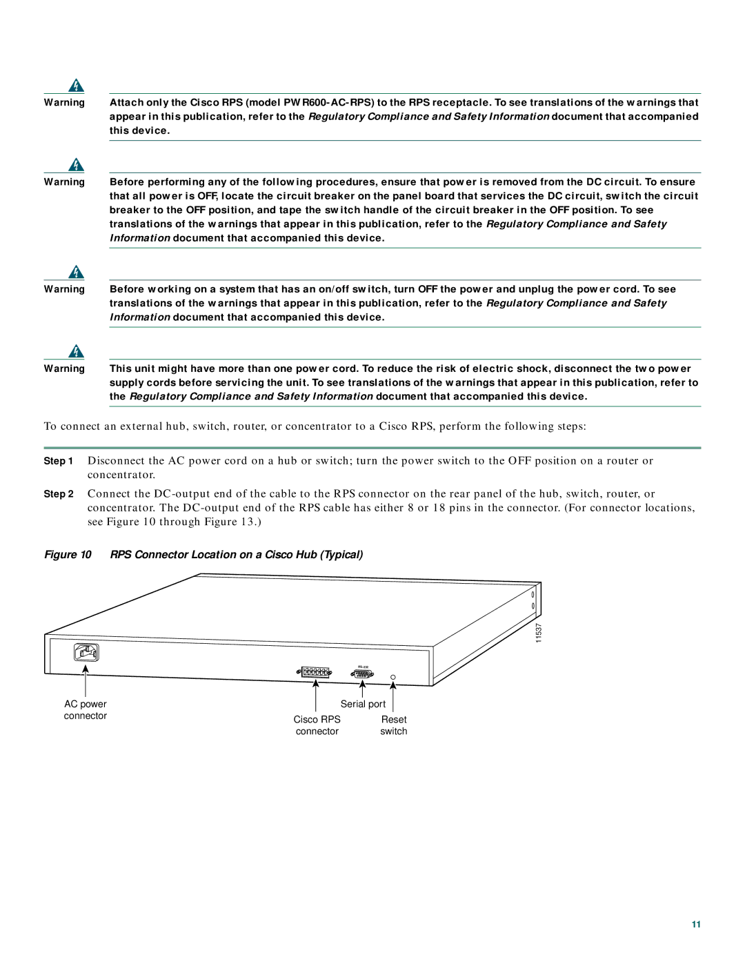
Step 2 Connect the
Figure 10 RPS Connector Location on a Cisco Hub (Typical)
11537
|
|
|
|
|
|
|
|
|
|
|
|
|
|
AC power |
|
| Serial port |
| ||
connector | Cisco RPS |
| Reset | |||
|
|
| ||||
|
| connector |
| switch | ||
11
