7513 specifications
The Cisco Systems 7513 is a robust router designed to address the demands of high-performance networking environments. Introduced as part of Cisco’s flagship 7500 Series, the 7513 is engineered to cater to enterprise and service provider requirements, delivering high availability, advanced traffic management capabilities, and exceptional scalability.One of the key features of the Cisco 7513 is its modular architecture. This design allows for a mix-and-match approach to network interfaces, meaning that organizations can customize their routing capabilities according to specific needs. The router supports a variety of interface cards, including Ethernet, ATM, and POS (Packet over SONET) options, enabling seamless integration into different network topologies.
The 7513 is powered by Cisco’s innovative IOS (Internetwork Operating System), which is renowned for its reliability and feature-rich capabilities. This OS supports advanced routing protocols, including BGP, OSPF, and EIGRP, ensuring efficient data handling and routing decisions across complex and geographically dispersed networks. Additionally, the router accommodates Quality of Service (QoS) features that prioritize network traffic to guarantee optimal performance for critical applications.
In terms of performance, the Cisco 7513 can handle substantial data throughput, equipped with a powerful processor and sufficient memory capacity to support dynamic routing table populations and extensive functionalities. It is capable of delivering a routing capacity that meets the needs of both small enterprises and large service providers, making it a flexible choice.
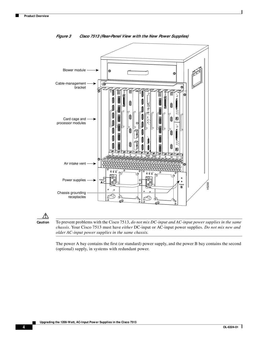
Another significant characteristic of the 7513 is its support for redundancy and failover mechanisms. With options for redundant power supplies and enhanced cooling systems, the router is designed to operate continuously, ensuring high availability and minimal downtime. Furthermore, it supports Cisco’s High Availability features, such as Stateful Switchover, enhancing network reliability.
Security is an essential aspect of any modern router, and the Cisco 7513 comes equipped with various built-in security functionalities. These include access control lists (ACLs), Network Address Translation (NAT), and support for Virtual Private Networks (VPNs), which enable organizations to secure their data transmissions effectively.
In summary, the Cisco Systems 7513 is a versatile, high-capacity modular router suitable for a wide range of networking applications. Its advanced features, reliability, and scalability make it a critical component for enterprises and service providers seeking to enhance their infrastructure and meet evolving bandwidth demands. With its capacity to support diverse technologies and protocols, the 7513 remains a cornerstone in the realm of professional networking solutions.

