Verifying the Installation
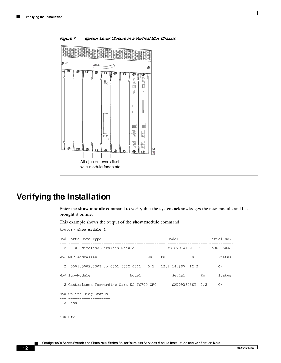
Figure 7 Ejector Lever Closure in a Vertical Slot Chassis
FAN
STATUS
![]() 24 PORT 100FX
24 PORT 100FX
![]()
STATUS
ACTIVE
NEXT | SELECT |
|
SUPERVISOR2
| STATUS |
| SYSTEM |
| CONSOLE |
| PWR |
| MGMT |
| RESET |
CONSOLE |
|
| MODE PORT CONSOLE |
PCMCIA |
|
EJECT |
|
1% | 100% |
| Switch |
| Load |
| PORT1 |
| PORT2 |
WS X6K- SUP2- 2GE-
SUPERVISOR2
| STATUS |
| SYSTEM |
| CONSOLE |
| PWR |
| MGMT |
| RESET |
CONSOLE |
|
| MODE PORT CONSOLE |
PCMCIA |
|
EJECT |
|
1% | 100% |
| Switch |
| Load |
| PORT1 |
| PORT2 |
63587
All ejector levers flush with module faceplate
Verifying the Installation
Enter the show module command to verify that the system acknowledges the new module and has brought it online.
This example shows the output of the show module command:
Router> show module 2
Mod | Ports Card Type |
|
| Model | Serial No. | ||
2 | 10 | Wireless Services Module |
| ||||
Mod | MAC addresses |
| Hw | Fw | Sw | Status | |
| |||||||
2 | 0001.0002.0003 to 0001.0002.0012 | 0.1 | 12.2(14r)S5 | 12.2 | Ok | ||
Mod | Model |
| Serial | Hw | Status | ||
2 | Centralized Forwarding Card | SAD092608SY 0.2 | Ok | ||||
Mod Online Diag Status
---
2 Pass
Router>
Catalyst 6500 Series Switch and Cisco 7600 Series Router Wireless Services Module Installation and Verification Note
12 |
| |
|