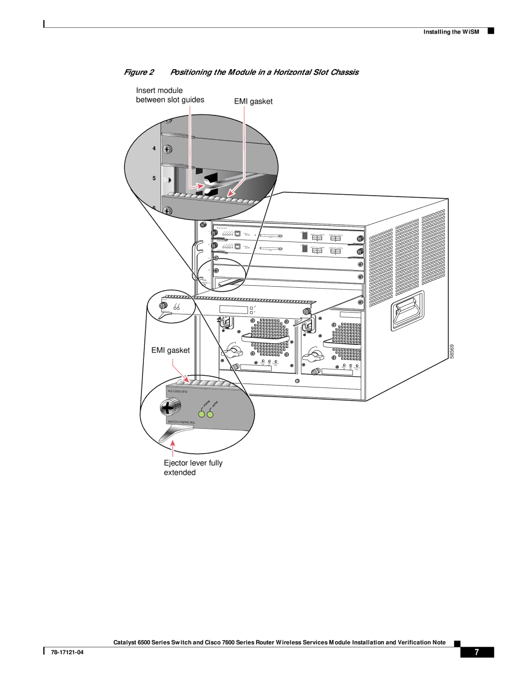
Figure 2 Positioning the Module in a Horizontal Slot Chassis
Insert module |
| |
between slot guides | EMI gasket | |
| 3 |
|
4 | 4 |
|
|
| |
5 | 5 |
|
|
| |
6![]() 6
6![]()
![]()
|
|
|
|
| |
1 |
|
| Switch | Load |
|
CONSOLE |
| 100% | PORT 1 |
| |
| PORT |
|
| PORT 2 | |
| MODE |
|
|
| |
| CONSOLE |
|
|
|
|
| SUPERVISOR2 | PCMCIA | EJECT |
|
|
|
|
| 1% |
|
|
|
|
|
|
| |
2 |
|
| Switch | Load |
|
CONSOLE |
| 100% | PORT 1 |
| |
| PORT |
|
| PORT 2 | |
| MODE |
|
|
| |
| CONSOLE |
|
|
|
|
| SUPERVISOR2 | PCMCIA | EJECT |
|
|
|
|
| 1% |
|
|
3
4
FAN
STATUS 5
24 PORT 100FX
EMI gasket | o |
| o |
|
|
|
|
|
|
| |
| INPUT | FAN | OUTPUT |
|
|
| OK | OK | FAIL |
|
|
|
|
| INPUT | FAN | OUTPUT |
|
|
| OK | OK | FAIL |
|
|
|
|
| |
| STATUS ACTIVE |
|
|
|
|
SWITCH FABRIC MDL |
|
|
|
|
|
Ejector lever fully extended
Installing the WiSM
58569
Catalyst 6500 Series Switch and Cisco 7600 Series Router Wireless Services Module Installation and Verification Note
| 7 |
| |
|
|
