Installing the Cisco SFS 7008P Switch into a Rack
Installing Optional High-Availability Components
If you purchased a
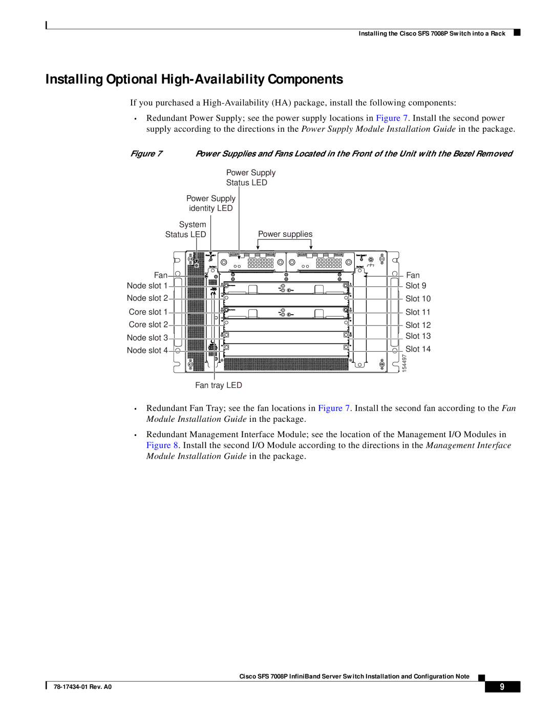
•Redundant Power Supply; see the power supply locations in Figure 7. Install the second power supply according to the directions in the Power Supply Module Installation Guide in the package.
Figure 7 | Power Supplies and Fans Located in the Front of the Unit with the Bezel Removed |
| Power Supply |
| Status LED |
Power Supply | |
identity LED | |
System |
|
Status LED | Power supplies |
Fan | Fan |
Node slot 1 | Slot 9 |
Node slot 2 | Slot 10 |
Core slot 1 ![]()
![]()
![]() Slot 11
Slot 11
Core slot 2 | Slot 12 |
Node slot 3 | Slot 13 |
Node slot 4 | Slot 14 |
| 154497 |
Fan tray LED
•Redundant Fan Tray; see the fan locations in Figure 7. Install the second fan according to the Fan Module Installation Guide in the package.
•Redundant Management Interface Module; see the location of the Management I/O Modules in Figure 8. Install the second I/O Module according to the directions in the Management Interface Module Installation Guide in the package.
Cisco SFS 7008P InfiniBand Server Switch Installation and Configuration Note
| 9 |
| |
|
|
