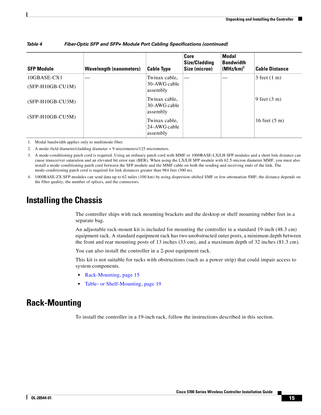
AIRCT576025K9, AIRCT5760HAK9 specifications
Cisco Systems has established itself as a leading provider in networking technology, with products designed to enhance connectivity and security in various environments. Among its diverse portfolio, the Cisco AIR-CT5760-HA-K9 and AIR-CT5760-25-K9 wireless controllers stand out for their advanced capabilities in managing wireless networks.The Cisco AIR-CT5760 series provides robust features that cater to the needs of modern enterprises requiring scalable, high-performance solutions. These controllers are designed to support up to 6,000 access points and 64,000 client devices, making them an ideal choice for large organizations with extensive wireless networks.
One of the standout features of the AIR-CT5760 is its support for Cisco's advanced mobility services architecture. This technology enables seamless roaming and handoff between access points, ensuring that end users maintain uninterrupted connectivity while moving throughout the coverage area. Additionally, the controllers leverage Cisco CleanAir technology, which actively detects and mitigates Wi-Fi interference by identifying non-Wi-Fi devices that can disrupt communication, thereby optimizing wireless performance.
Security is a paramount consideration in today's digital landscape, and the AIR-CT5760 series addresses this concern with integrated security features. It supports Cisco Identity Services Engine (ISE), enabling context-aware access control and policy enforcement, ensuring that only authorized users and devices can connect to the network. The controllers also support advanced encryption protocols to secure data transmissions over wireless connections.
Another significant characteristic of the AIR-CT5760 series is its support for multi-vendor environments. Utilizing the OpenFlow protocol and the Cisco Wireless LAN Controller technology, these controllers can manage access points from various manufacturers, providing a flexible solution for diverse networking environments.
High availability is critical for mission-critical applications, and the AIR-CT5760-HA-K9 model offers redundancy features to ensure continuous operation. The controller can be configured in a high-availability pair, allowing for automatic failover in the event of hardware failure, thus minimizing downtime.
Moreover, the AIR-CT5760 series emphasizes ease of management through Cisco Prime Infrastructure, providing an intuitive interface for network administrators to deploy, monitor, and troubleshoot the wireless network, thereby enhancing operational efficiency.
In conclusion, the Cisco AIR-CT5760-HA-K9 and AIR-CT5760-25-K9 wireless controllers deliver sophisticated solutions tailored for the demands of enterprise wireless networking. With their scalability, advanced security measures, and support for a multi-vendor ecosystem, these controllers are pivotal in building reliable, high-performing wireless networks that drive business success.

