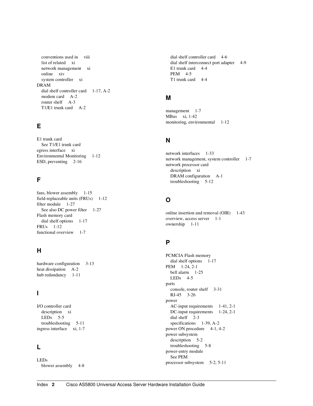
AS5800 specifications
Cisco Systems has long been a leader in the networking and telecommunications field, and its AS5800 series of routers exemplify this tradition. The AS5800, along with the AS5850, AS5350, AS5400, and AS5300, provides robust solutions for service providers and enterprise-level networking applications. Each of these models has distinct features and characteristics that cater to the evolving demands of internet traffic and data processing.The Cisco AS5800 is designed for high-capacity routing and optimized for broadband services. It supports a wide range of services, including voice, data, and video applications, making it a versatile option for service providers looking to deliver integrated solutions. It is equipped with advanced quality of service (QoS) features that ensure bandwidth is allocated effectively, holding strong even under heavy traffic conditions.
In comparison, the AS5850 offers superior processing capabilities and is typically utilized in larger-scale implementations. This model supports high-density interfaces, allowing numerous connections without compromising performance. Its architecture includes enhanced MPLS (Multiprotocol Label Switching) support, enabling more efficient traffic management and better utilization of network resources.
The AS5350 is known for its scalability and energy efficiency, ideal for voice-over-IP (VoIP) and media gateway applications. It supports various telephony features, such as protocol interworking and transcoding, making it a preferred choice for organizations focusing on digital voice technologies. The AS5300, while slightly older, continues to be a valuable asset for less demanding networks, offering reliable performance with VoIP capabilities and basic data applications.
The AS5400 bridges the gap between high-performance routing and operational efficiency. It incorporates Cisco's proprietary technologies to ensure seamless connectivity and robust failover systems. This model is highly regarded for its security features, protecting network integrity and providing peace of mind for businesses relying on sensitive data transfer.
Overall, Cisco’s AS5800 series showcases a progressive evolution of routing capabilities with enhanced features tailored for resilience, scalability, and performance. These routers not only address the technical needs of modern networks but also strategically position organizations for future growth in an increasingly digital world. Each model, with its unique attributes, continues to support the varied demands of global communication infrastructures.
