Chapter 1 Cisco AS5850 Product Overview
Cisco AS5850 Chassis
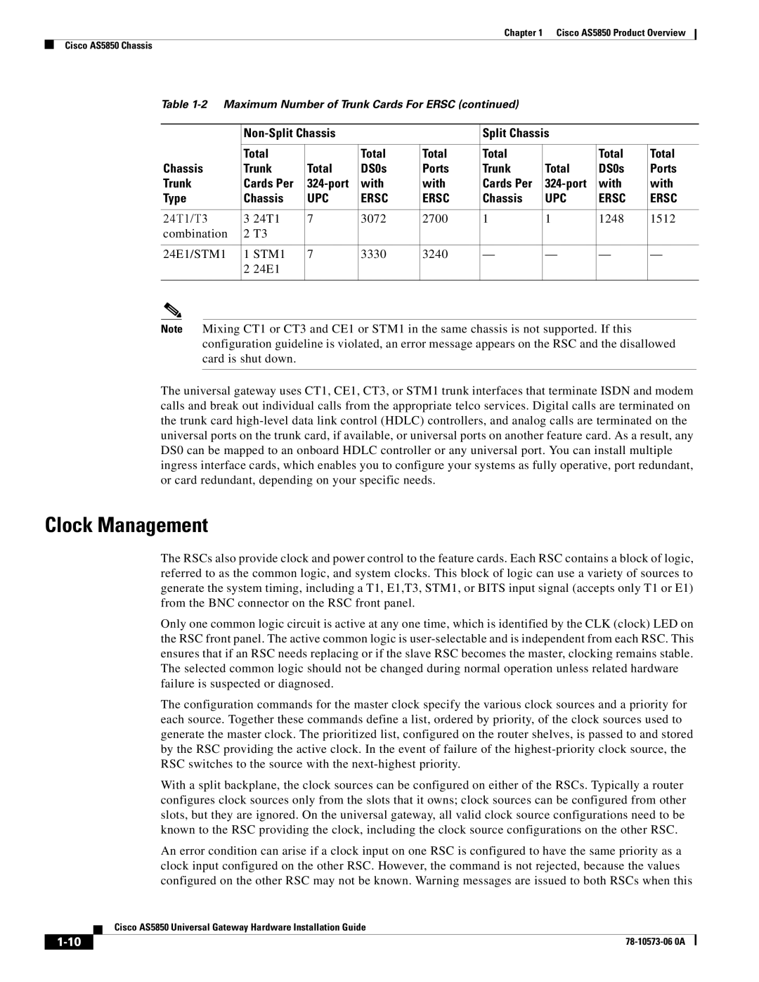
Table
|
|
| Split Chassis |
|
| ||||
|
|
|
|
|
|
|
|
| |
| Total |
| Total | Total | Total |
| Total | Total | |
Chassis | Trunk | Total | DS0s | Ports | Trunk | Total | DS0s | Ports | |
Trunk | Cards Per | with | with | Cards Per | with | with | |||
Type | Chassis | UPC | ERSC | ERSC | Chassis | UPC | ERSC | ERSC | |
|
|
|
|
|
|
|
|
|
|
24T1/T3 | 3 | 24T1 | 7 | 3072 | 2700 | 1 | 1 | 1248 | 1512 |
combination | 2 | T3 |
|
|
|
|
|
|
|
|
|
|
|
|
|
|
|
| |
24E1/STM1 | 1 STM1 | 7 | 3330 | 3240 | — | — | — | — | |
| 2 | 24E1 |
|
|
|
|
|
|
|
|
|
|
|
|
|
|
|
|
|
Note Mixing CT1 or CT3 and CE1 or STM1 in the same chassis is not supported. If this configuration guideline is violated, an error message appears on the RSC and the disallowed card is shut down.
The universal gateway uses CT1, CE1, CT3, or STM1 trunk interfaces that terminate ISDN and modem calls and break out individual calls from the appropriate telco services. Digital calls are terminated on the trunk card
Clock Management
The RSCs also provide clock and power control to the feature cards. Each RSC contains a block of logic, referred to as the common logic, and system clocks. This block of logic can use a variety of sources to generate the system timing, including a T1, E1,T3, STM1, or BITS input signal (accepts only T1 or E1) from the BNC connector on the RSC front panel.
Only one common logic circuit is active at any one time, which is identified by the CLK (clock) LED on the RSC front panel. The active common logic is
The configuration commands for the master clock specify the various clock sources and a priority for each source. Together these commands define a list, ordered by priority, of the clock sources used to generate the master clock. The prioritized list, configured on the router shelves, is passed to and stored by the RSC providing the active clock. In the event of failure of the
With a split backplane, the clock sources can be configured on either of the RSCs. Typically a router configures clock sources only from the slots that it owns; clock sources can be configured from other slots, but they are ignored. On the universal gateway, all valid clock source configurations need to be known to the RSC providing the clock, including the clock source configurations on the other RSC.
An error condition can arise if a clock input on one RSC is configured to have the same priority as a clock input configured on the other RSC. However, the command is not rejected, because the values configured on the other RSC may not be known. Warning messages are issued to both RSCs when this
| Cisco AS5850 Universal Gateway Hardware Installation Guide |