Chapter 1 Cisco AS5850 Product Overview
Table
LED Indicator | Display | Description |
|
|
|
MAINT | Yellow | Flashing indicates that diagnostics are |
|
| currently running. On indicates that the RSC |
|
| failed diagnostics or was shut down for |
|
| removal. This LED is normally off. |
|
|
|
ALARM | Yellow | Comes on to indicate a major1 or minor2 alarm |
|
| condition. |
|
|
|
Clock and Status LEDs |
|
|
|
|
|
MAST (master) | Green | RSC is in |
|
|
|
CLK (clock) | Green | Comes on to identify the route switch control- |
|
| ler card active clock; active clock is indepen- |
|
| dent from master route switch controller card |
|
| designation. |
|
|
|
FLASH | Green | Comes on when compact Flash slot is in use. |
|
|
|
LINK | Green | Indicates valid Ethernet link has been estab- |
|
| lished. |
|
|
|
ACT | Green | Indicates traffic activity on the Ethernet. |
|
|
|
Liquid Crystal Displays |
|
|
|
|
|
LCDs (upper and lower) | Alphanumeric; | Displays SPLT if in |
| 4 characters | HSPL if in |
| each |
|
|
|
|
1.A major alarm condition includes RSC failure, backplane failure, fan failure, power module failure, feature card failure, or conditional environmental thresholds.
2.A minor alarm condition includes modem SIMM failure, HDLC controller failure, trunk line failure, or conditional en- vironmental thresholds.
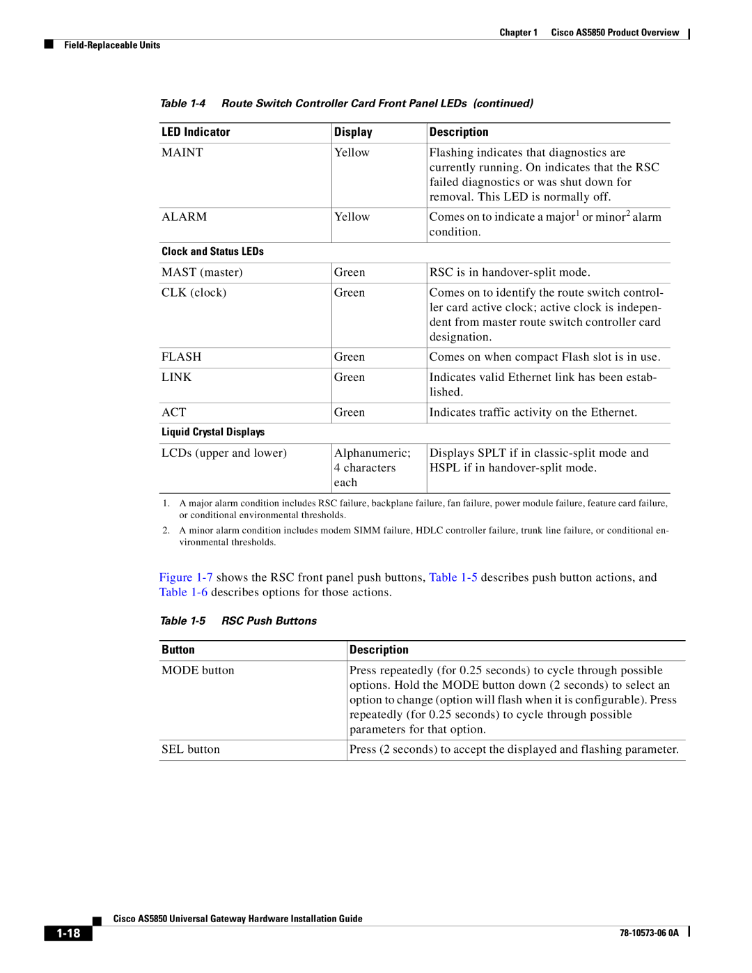
Figure 1-7 shows the RSC front panel push buttons, Table 1-5 describes push button actions, and Table 1-6 describes options for those actions.
Table
Button | Description |
|
|
MODE button | Press repeatedly (for 0.25 seconds) to cycle through possible |
| options. Hold the MODE button down (2 seconds) to select an |
| option to change (option will flash when it is configurable). Press |
| repeatedly (for 0.25 seconds) to cycle through possible |
| parameters for that option. |
|
|
SEL button | Press (2 seconds) to accept the displayed and flashing parameter. |
|
|
| Cisco AS5850 Universal Gateway Hardware Installation Guide |
