Chapter 1 Cisco AS5850 Product Overview
System Components
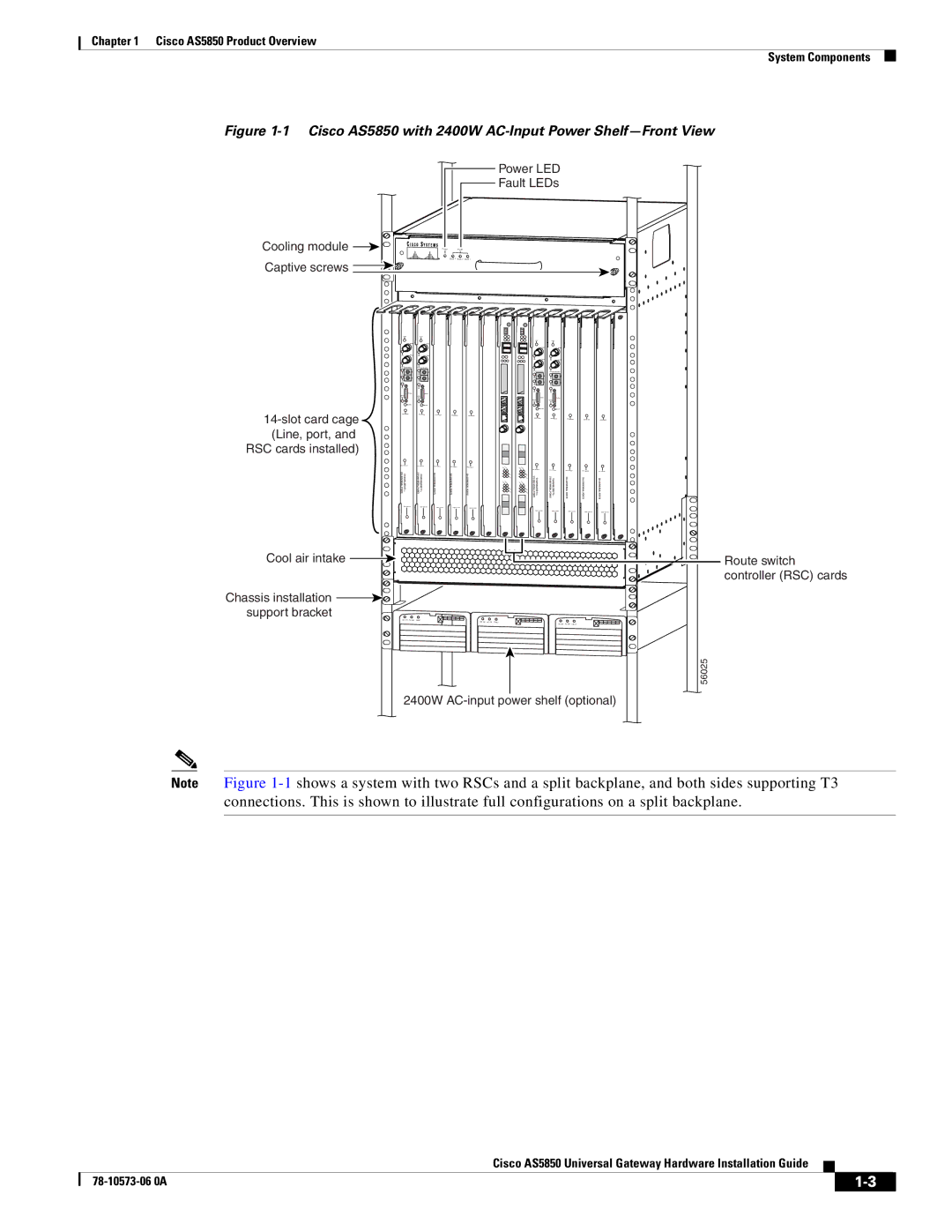
Figure 1-1 Cisco AS5850 with 2400W AC-Input Power Shelf—Front View
![]() Power LED
Power LED
![]() Fault LEDs
Fault LEDs
Cooling module | Power | Fault |
|
| Bank 1 | Bank 2 | Bank 3 |
Captive screws |
|
|
|
CHANNELIZED T3 + 216 UNIVERSAL PORTS | CHANNELIZED T3 + 216 UNIVERSAL PORTS | 324 UNIVERSAL PORTS | 324 UNIVERSAL PORTS | 324 UNIVERSAL PORTS | CHANNELIZED T3 + 216 UNIVERSAL PORTS | CHANNELIZED T3 + 216 UNIVERSAL PORTS | 324 UNIVERSAL PORTS | 324 UNIVERSAL PORTS | 324 UNIVERSAL PORTS |
Cool air intake ![]()
Chassis installation ![]()
![]() support bracket
support bracket
DC OK AC OK FAULT
DC OK AC OK FAULT
DC OK AC OK FAULT
56025
2400W
Route switch controller (RSC) cards
Note Figure
|
| Cisco AS5850 Universal Gateway Hardware Installation Guide |
|
| |
|
|
| |||
|
|
|
| ||
|
|
|
| ||