Chapter 1 Cisco AS5850 Product Overview
Table
Function | Definition |
|
|
ACO YES/NO | ALARM |
| external alarm relay control bits. If any subsequent (new) alarm condition |
| occurs, ACO status should revert to NO. |
|
|
ALARM: | When selected, turns off the HIST LED (if it is on), but only if there is no |
HIST CLEAR | current Major or Minor alarm condition. |
|
|
RSC STOP/START | Select this before removing the RSC card. |
|
|
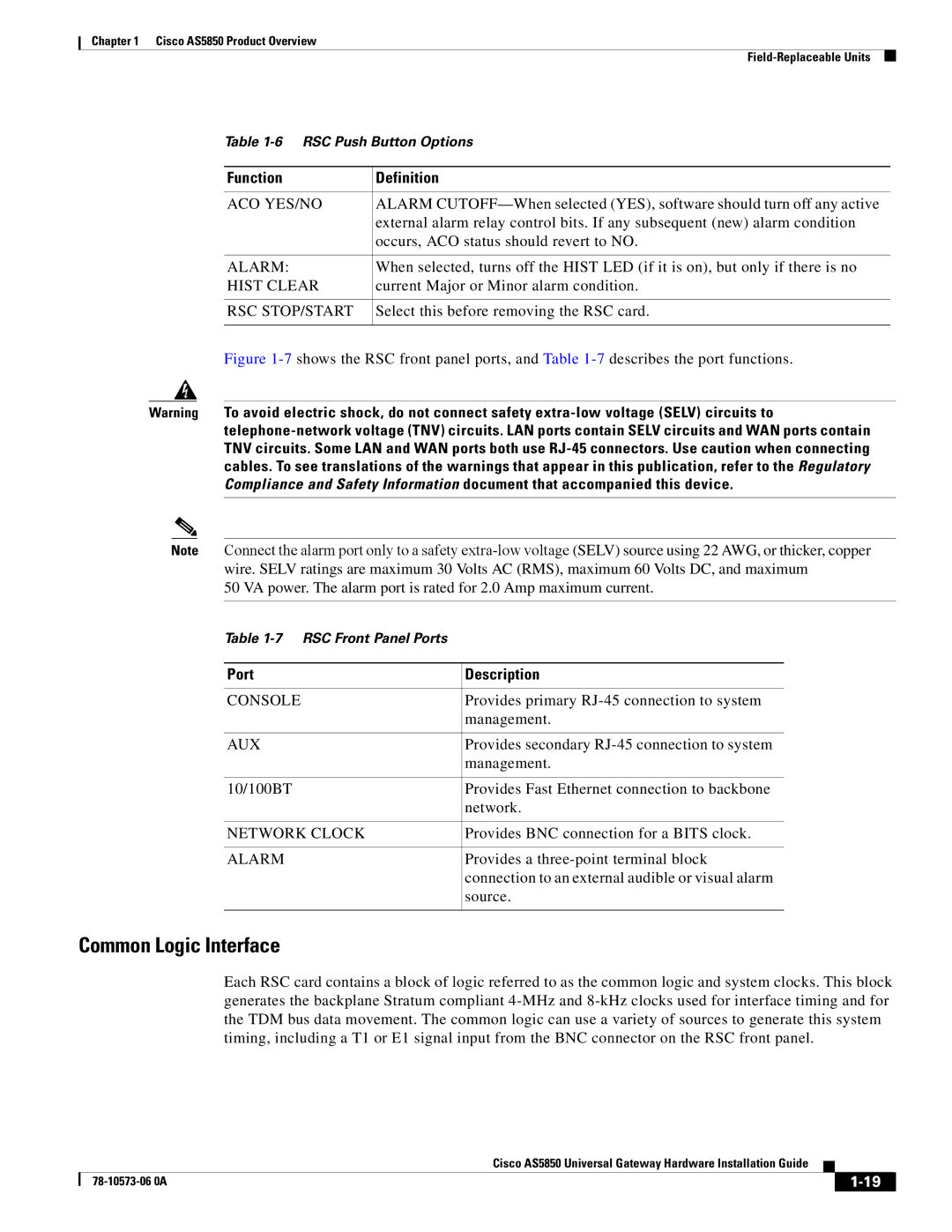
Figure 1-7 shows the RSC front panel ports, and Table 1-7 describes the port functions.
Warning To avoid electric shock, do not connect safety
Note Connect the alarm port only to a safety
50 VA power. The alarm port is rated for 2.0 Amp maximum current.
Table
Port | Description |
|
|
CONSOLE | Provides primary |
| management. |
|
|
AUX | Provides secondary |
| management. |
|
|
10/100BT | Provides Fast Ethernet connection to backbone |
| network. |
|
|
NETWORK CLOCK | Provides BNC connection for a BITS clock. |
|
|
ALARM | Provides a |
| connection to an external audible or visual alarm |
| source. |
|
|
Common Logic Interface
Each RSC card contains a block of logic referred to as the common logic and system clocks. This block generates the backplane Stratum compliant
|
| Cisco AS5850 Universal Gateway Hardware Installation Guide |
|
| |
|
|
| |||
|
|
|
| ||
|
|
|
| ||
