ASA 5500 specifications
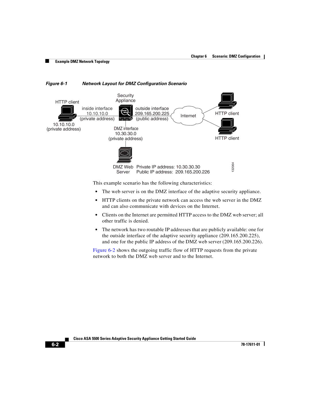
Cisco Systems ASA 5500 is a robust security appliance designed to provide advanced network security and protection against both internal and external threats. Ideal for organizations of various sizes, the ASA 5500 series offers a wide range of features that combine firewall capabilities with intrusion prevention, VPN support, and application control, among others.One of the key features of the ASA 5500 is its stateful firewall technology. This allows the device to monitor active connections and enforce security policies based on the state of the traffic. By maintaining the context of network sessions, the firewall can make informed decisions on whether to allow or deny traffic based on established rules.
In addition to traditional firewall functionalities, the ASA 5500 series integrates advanced intrusion prevention capabilities. By analyzing traffic patterns and identifying known threats, the IPS functionality helps organizations defend against a variety of malicious activities, such as DDoS attacks, malware, and unauthorized access attempts. The ASA 5500 continuously updates its threat intelligence through Cisco's global threat database, enhancing its ability to detect emerging threats in real-time.
Virtual Private Network (VPN) support is another significant aspect of the ASA 5500 series. The device offers secure, encrypted connections for remote users and branch offices, ensuring safe access to corporate resources over the Internet. It supports both IPsec and SSL VPN protocols, allowing organizations to choose the best option for their specific needs. This capability is crucial for businesses that require a secure environment for remote work.
The ASA 5500 series also features extensive application control and visibility tools. These tools enable organizations to manage and control the applications running on their network, ensuring that only authorized applications can communicate through the firewall. This level of control helps to mitigate risks associated with unauthorized applications, which can lead to data breaches or reduced productivity.
Moreover, the ASA 5500 is designed with high availability and scalability in mind. Its clustering support ensures that multiple units can work together to provide redundancy and load balancing, enhancing both performance and reliability. This characteristic is especially important for organizations looking to maintain continuous operation during traffic spikes or hardware failures.
In summary, Cisco Systems ASA 5500 is an all-in-one security solution that combines stateful firewall protection, intrusion prevention, VPN capabilities, and application control. With its robust feature set and focus on security, it is well-suited for organizations seeking to protect their networks from an ever-evolving landscape of cyber threats. Whether for small businesses or large enterprises, the ASA 5500 provides the necessary tools to create a secure networking environment.

