Connect the Power Supply
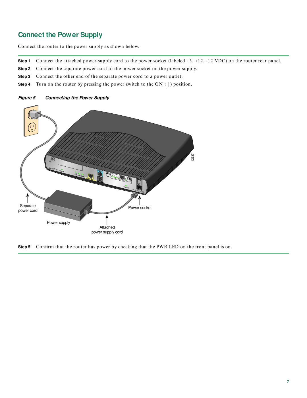
Connect the router to the power supply as shown below.
Step 1 Connect the attached
Step 3 Connect the other end of the separate power cord to a power outlet.
Step 4 Turn on the router by pressing the power switch to the ON ( ) position.
Figure 5 Connecting the Power Supply
Cisco |
|
|
|
|
|
|
|
|
|
|
|
|
|
|
1720 | WIC0 | OK |
|
|
| CONSOLE |
|
|
|
|
|
|
|
|
|
| FDX | 100 | LNK |
| TD | RD |
|
|
|
|
|
|
|
|
|
|
| LP | AL |
|
|
|
|
| ||||
|
|
|
|
|
|
|
|
|
| |||||
|
|
|
| 10/100 | ETHERNET |
| SEE | MANUAL |
|
|
|
|
|
|
|
|
|
|
|
|
|
|
| INSTALLATION | DSU |
|
|
| |
|
|
|
|
|
|
|
|
| BEFORE |
| CD |
|
|
|
|
|
|
|
|
| AUX |
|
|
|
| 56K |
|
|
|
|
|
|
|
|
|
|
|
|
|
|
|
|
| |
|
|
|
|
|
|
|
|
|
| WIC |
|
|
| |
|
|
|
|
|
|
|
|
|
|
| 1OK |
|
|
|
|
|
|
|
|
|
|
|
|
|
| +5, | +12, | VDC | |
|
|
|
|
|
|
|
|
|
|
|
| |||
|
|
|
|
|
|
|
|
|
|
|
|
|
| |
|
|
|
|
|
|
|
|
|
|
Separate |
|
|
| |
| Power socket | |||
power cord |
| |||
|
|
| ||
|
|
| ||
|
| Power supply |
| |
|
| Attached | ||
|
| power supply cord | ||
![]()
![]()
![]()
![]()
![]()
![]()
![]()
![]()
![]() 12237
12237
Step 5 Confirm that the router has power by checking that the PWR LED on the front panel is on.
7
